Eureka AIR delivers breakthrough ideas for toughest innovation challenges, trusted by R&D personnel around the world.

Synchronization system and method for detecting optical fiber asymmetry and master-slave optical module equipment

An asymmetric and optical module technology, applied in the direction of photonic/optical synchronization, transmission monitoring/testing/fault measurement system, transmission system, etc., can solve the problems of poor accuracy, reliability, difficulty, and high execution complexity, and achieve The effect of reducing execution complexity, reducing test time, and improving test accuracy

Active Publication Date: 2017-06-27
ZTE CORP
View PDF5 Cites 0 Cited by
  • Summary
  • Abstract
  • Description
  • Claims
  • Application Information

AI Technical Summary

Problems solved by technology

The optical time domain reflectometer (OTDR) technology is a solution to the ranging system made of Rayleigh scattering and Fresnel reflection when the light pulse is transmitted in the optical fiber. However, the OTDR technology It is a long-distance test, the test time is long, and the execution complexity is high, so it cannot respond quickly, resulting in poor accuracy and reliability, and it is also very difficult to integrate into the optical module

Method used


Image

  • Synchronization system and method for detecting optical fiber asymmetry and master-slave optical module equipment
  • Synchronization system and method for detecting optical fiber asymmetry and master-slave optical module equipment
  • Synchronization system and method for detecting optical fiber asymmetry and master-slave optical module equipment

Examples


Embodiment Construction

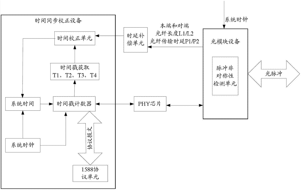
[0053] The basic idea of ​​the present invention is to detect the asymmetric distance and pulse transmission delay difference of the two-way optical fiber between the network elements at both ends, and obtain the asymmetric time delay of the bidirectional optical fiber according to the asymmetric distance of the bidirectional optical fiber and the pulse transmission time delay difference, The system time is corrected by compensating according to the asymmetric time delay of the two-way optical fiber, and the time synchronization of the optical fiber asymmetry is realized.

[0054] The present invention mainly comprises the following contents:

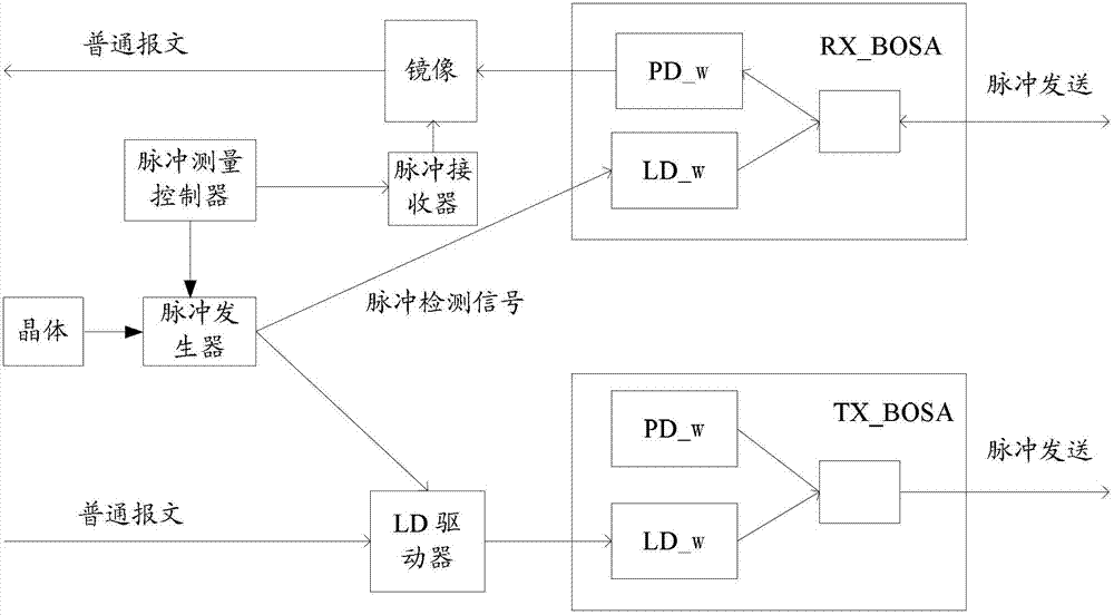
[0055] A synchronization system for detecting optical fiber asymmetry, comprising an optical module device integrated with a pulse asymmetry detection unit, a delay compensation unit, a time synchronization correction device, and a physical layer (PHY) chip. Among them, the optical module device in the system is a new device; the delay ...


PUM


Abstract

The invention discloses a synchronization system for detecting optical fiber asymmetry, comprising: time synchronization correction equipment, delay compensation unit, optical module equipment, the optical module equipment is used to detect the asymmetric distance and The pulse transmission time delay difference is to obtain the asymmetric time delay of the bidirectional fiber according to the asymmetric distance of the bidirectional fiber and the pulse transmission time delay difference. The invention also discloses a synchronization method for detecting the asymmetry of the optical fiber, which comprises obtaining the asymmetric time delay of the bidirectional optical fiber according to the asymmetric distance of the bidirectional optical fiber and the difference of the pulse transmission time delay. The invention also discloses a master optical module device and a slave optical module device for detecting optical fiber asymmetry. The system and method of the invention can reduce test time and implementation complexity, thereby enabling rapid response and improving test accuracy.

Description

technical field [0001] The invention relates to time synchronization technology, in particular to a synchronization system and method for detecting optical fiber asymmetry, master optical module equipment and slave optical module equipment. Background technique [0002] Due to the need for time technology in wireless time division duplex (TDD, Time Division Duplexing) services, the implementation of the 1588 protocol based on synchronous Ethernet has gradually become the mainstream technology of time synchronization technology in the communication industry. [0003] However, since the 1588 time synchronization technology relies on the two-way symmetry of the intermediate path transmission delay between synchronization nodes in principle, it is a two-way asymmetry in the current network, that is, due to the error of the fiber core of the optical cable, the connection error of the optical cable construction, and the connection error of the optical cable fault , pigtail errors ...

Claims


Application Information

Patent Timeline
Patent Type & Authority Patents(China)
IPC IPC(8): H04J3/06H04B10/07
CPCH04L5/1469H04J3/0667H04B10/27H04B10/073H04B10/0795H04J3/0682H04L7/0075
Inventor 何力石鸿斌
Owner ZTE CORP
Why Eureka
Eureka Blog
Learn More