Metal liquid-solid interface thermal extrusion welding method

A technology of extrusion welding and interface heating, which is applied in the direction of welding equipment, welding equipment, auxiliary welding equipment, etc., can solve the problems of long process cycle time, complicated process, difficult and low-cost assembly line welding, etc., and achieve low cost and high welding efficiency The process is simple and the effect of improving the welding strength

Active Publication Date: 2014-06-11
上海亚仕龙能源科技有限公司
View PDF5 Cites 5 Cited by
  • Summary
  • Abstract
  • Description
  • Claims
  • Application Information

AI Technical Summary

Problems solved by technology

Since this welding method is implemented in a vacuum heating furnace using a crucible, the process is complex and the process cycle time is long, it is difficult to achieve low-cost assembly line welding

Method used


Image

  • Metal liquid-solid interface thermal extrusion welding method
  • Metal liquid-solid interface thermal extrusion welding method
  • Metal liquid-solid interface thermal extrusion welding method

Examples


Embodiment 1

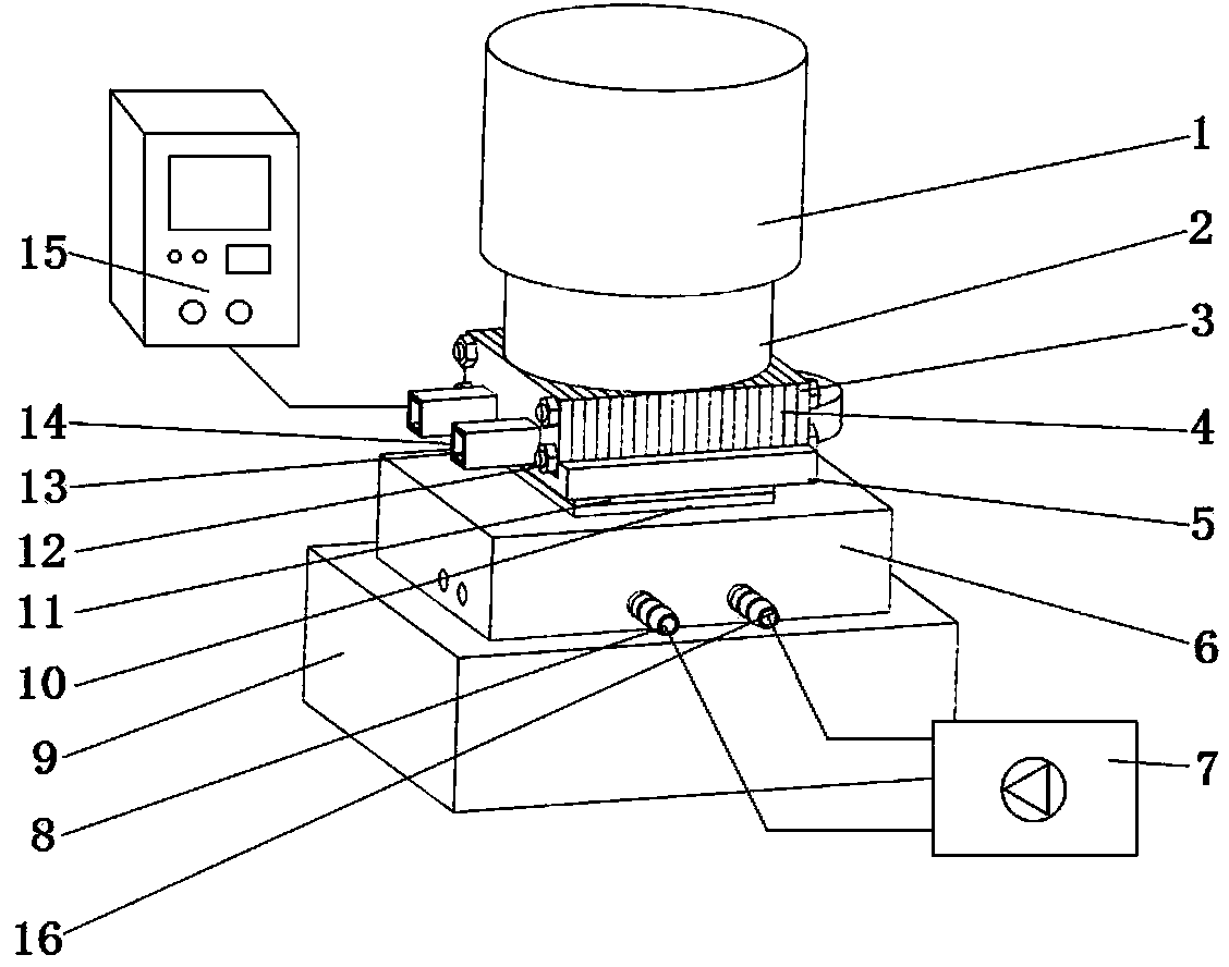
[0032] Embodiment 1: The liquid metal solid interface hot extrusion welding method in this embodiment is used to weld two metal weldments into one, and is applicable to two metal weldments made of dissimilar metals. This method can be used as figure 1 A welding device implementation is shown, but is not limited to this type of device.

[0033] like figure 1 As shown, the welding method of this embodiment is used to weld the first metal weldment 10 and the second metal weldment 11 into one body. The melting point of the metal weldment 11, the welding method specifically includes:

[0034] The first metal weldment 10 is embedded in an accommodating cavity 17 that matches its shape and size and the depth of the cavity is smaller than the height of the first metal weldment 10. At this time, the upper surface (ie, the welding surface) of the first metal weldment 10 is exposed On the upper opening of the accommodating cavity 17 . The welding surfaces of the second metal weldment...

Embodiment 2

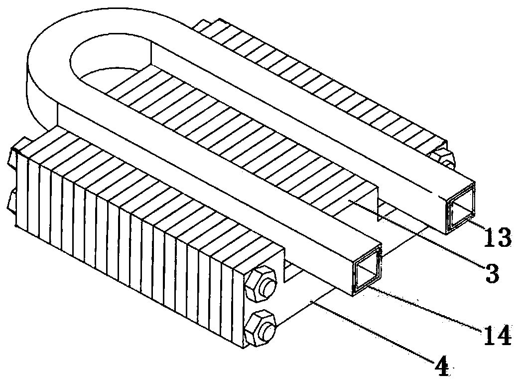
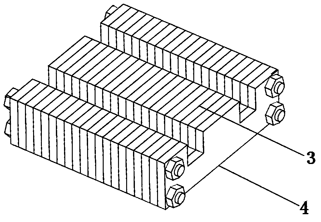
[0037]Embodiment 2: Compared with Embodiment 1, this embodiment is different in that this embodiment is aimed at the welding requirements between two metal weldments made of the same metal. In order to weld two metal weldments made of the same metal, the two metal weldments need to be respectively embedded in the accommodating cavities 17 of the two weldment dies 6, and the magnetic conduction pressure carrier 4 and the medium and high frequency The heating device composed of induction heating coil 13 can be arranged on one side of the welding surface where the two metal weldments are attached or on the back side of one of the accommodating cavities 17, so that the two metal weldments are partially heated to make the welding surfaces of the two Melting, at this moment, the rest of the metal weldment can be kept in a solid state by cooling the cooling channels provided in the respective weldment dies 6 .

[0038] When this embodiment is implemented in detail: the first metal we...


PUM


Abstract

The invention relates to the field of a metal combining process, in particular to a metal liquid-solid interface thermal extrusion welding method. The metal liquid-solid interface thermal extrusion welding method is characterized by comprising the following steps of embedding at least one metal welding part in a containing cavity matched with the welding part in shape and size, wherein the depth of the cavity body is smaller than the height of the welding part; arranging a pressure source, wherein the pressure source continuously applies pressure to the metal welding parts to tightly fit the welding surfaces of the two welding parts; adopting a heating coil with a magnetism guiding carrying pressing body to heat at least one of the metal welding part, wherein the heating temperature is not smaller than the melting point of the metal welding part with the lower melting point. The metal liquid-solid interface thermal extrusion welding method has the advantages of suitability for the welding of the same or different metal parts, fast welding speed, high welding strength, suitability for welding the combining areas of any size, and capability of welding the metal parts with any complex shape.

Description

technical field [0001] The invention relates to the field of metal bonding technology, in particular to a hot extrusion welding method for liquid metal solid interface. Background technique [0002] The dissimilar metal combined structure has both the excellent physical, mechanical and mechanical properties of dissimilar materials. It has a wide range of applications in the field of power electronics industry. The difference in physical and chemical properties of dissimilar metals brings difficulties to welding. At present, there are two types of industrial methods and processes that can realize the combination of dissimilar metals: welding and casting and forging. Welding methods include friction welding, brazing, diffusion welding, explosive welding, etc. Casting and forging methods include cold forging in a reduced state, hot extrusion and die casting. The above-mentioned welding method is mainly suitable for welding or combining large-area and large-volume dissimilar ...

Claims


Application Information

Patent Timeline
Patent Type & Authority Applications(China)
IPC IPC(8): B23K20/00B23K20/22
CPCB23K20/023B23K20/26B23K37/003B23K2103/18
Inventor 王子延刘小稚
Owner 上海亚仕龙能源科技有限公司
Why Eureka
Try Eureka