
Mode interference annular cavity optical fiber laser sensor

A fiber laser and mode interference technology, which is applied in the field of optoelectronics, can solve the problems that mode interference fiber sensors cannot be applied, and fiber grating laser sensors are cross-sensitive to temperature and strain. effect achieved

Active Publication Date: 2014-06-11
HARBIN INST OF TECH AT WEIHAI +1
View PDF8 Cites 11 Cited by
  • Summary
  • Abstract
  • Description
  • Claims
  • Application Information

AI Technical Summary

Problems solved by technology

[0003] In order to solve the problems of temperature and strain cross-sensitivity of fiber grating laser sensors in the background technology, and the inability of mode interference fiber sensors to be applied to high-precision and high-resolution sensing applications, the purpose of the present invention is to design and prepare a new type of mode Interference ring cavity fiber laser sensor, the mode interference fiber structure composed of multimode fiber and single-mode fiber connected on both sides is used as the mode selection element of the fiber laser resonator, and at the same time as the external physical quantity sensitive element, making a high signal-to-noise ratio, high Functional fiber laser sensor with high precision and no temperature-strain cross-sensitivity

Method used


Image

  • Mode interference annular cavity optical fiber laser sensor
  • Mode interference annular cavity optical fiber laser sensor
  • Mode interference annular cavity optical fiber laser sensor

Examples


Embodiment Construction

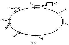
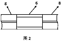
[0015] In order to further illustrate the technical characteristics of the present invention, the present invention will be described in detail below in conjunction with the accompanying drawings and specific embodiments, figure 1 Schematic diagram of the structure of the mode interference ring cavity fiber laser sensor. The device of the present invention includes: pump source 1, wavelength division multiplexer 2, rare earth doped active fiber 3, output coupler 4, polarization controller 5, multimode fiber 6, fiber isolator 7, single-mode transmission Fiber 8. The optical fiber fusion technology is used to connect the output ends of each part of the optical fiber, and the multimode optical fiber part is packaged as a sensing probe to form a mode interference ring cavity optical fiber laser sensor.

[0016] 1) The pump source 1 adopts a single-mode fiber-coupled semiconductor laser with an operating wavelength of 980nm / 1480nm. The output fiber of the pump source 1 is fused wi...


PUM


Abstract

The invention relates to a mode interference annular cavity optical fiber laser sensor. The mode interference annular cavity optical fiber laser sensor comprises a pumping source, a wavelength division multiplexer, a rare earth doped active optical fiber, an output coupler, a polarization controller, a multimode optical fiber, an optical fiber isolator and a single-mode transmission optical fiber. A sensing probe is formed by packaging a mode interference structure formed by the multimode optical fiber and the single-mode optical fiber, and the mode interference structure is used as a filtering element of the annular cavity optical fiber laser sensor and meanwhile responds to physical quantities of external displacement, external temperature, external strain and the like. When various physical quantities act on the sensor, the output wavelength and the output power of the laser sensor can drift, sensing information is acquired by detecting the laser output wavelength ad the laser output power, and the physical quantities can be measured in a high precision mode. The mode interference annular cavity optical fiber laser sensor is easy to manufacture and package, low is cost, high in signal to noise ratio and unit bandwidth power, and free of the temperature strain cross sensitivity influence, and can reliably work.

Description

technical field [0001] The invention belongs to the field of optoelectronic technology, relates to fiber optic laser sensing and other aspects, is related to fiber optic sensors, tunable fiber lasers, fiber optic filters, etc., and relates to the design and manufacture of a new fiber optic laser sensor. The fiber optic laser sensor involved in the present invention It is suitable for measuring various physical quantities such as displacement, temperature and strain. Background technique [0002] The fiber laser sensor organically combines the fiber sensor and the fiber laser, so that it not only has the advantages of optical fiber as the transmission medium of light and the "transmission and sensing" of the sensitive medium, but also has a high output signal-to-noise ratio. , narrow line width, low noise, high power per unit bandwidth, without broadband light source, can achieve high sensitivity, high resolution and high precision sensing, and has incomparable advantages in ...

Claims


Application Information

Patent Timeline
Patent Type & Authority Applications(China)
IPC IPC(8): G01D5/353
Inventor 潘玉寨黄雪骄苗杰光王玉宝
Owner HARBIN INST OF TECH AT WEIHAI
Learn More