Microscopic method based on wide field stimulated emission difference and microscopic device based on wide field stimulated emission difference

A stimulated emission, wide-field technology, applied in the field of super-resolution microscopy, can solve the problem of reducing the effective signal light luminous area, etc., and achieve the effects of easy operation, convenient data processing, and simple device structure

Inactive Publication Date: 2014-06-11
ZHEJIANG UNIV
View PDF7 Cites 12 Cited by
  • Summary
  • Abstract
  • Description
  • Claims
  • Application Information

AI Technical Summary

Problems solved by technology

[0004] Compared with conventional optical microscopy methods, FED reduces the luminous area of ​​effective signal light and achi

Method used


Image

  • Microscopic method based on wide field stimulated emission difference and microscopic device based on wide field stimulated emission difference
  • Microscopic method based on wide field stimulated emission difference and microscopic device based on wide field stimulated emission difference
  • Microscopic method based on wide field stimulated emission difference and microscopic device based on wide field stimulated emission difference

Examples


Embodiment 1

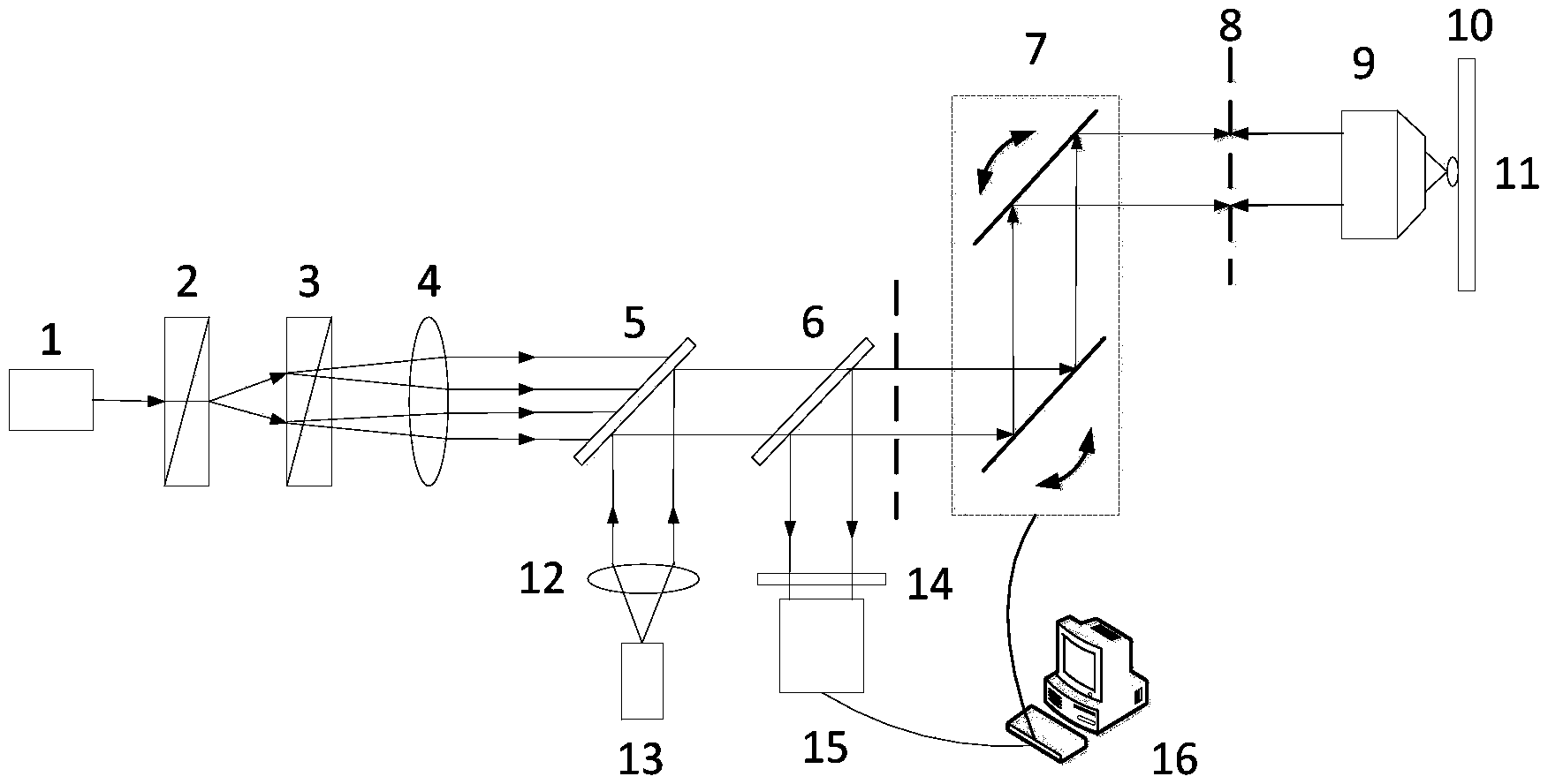
[0039] Such as figure 1 As shown, a microscope device based on wide-field stimulated emission difference for fluorescent samples, including a second laser 1, a first Wollaston prism 2, a second Wollaston prism 3, and a second lens 4, First dichroic mirror 5, second dichroic mirror 6, scanning vibrating mirror 7, objective lens 9, sample 10, sample stage 11, first lens 12, first laser 13, filter 14, detector 15, computer 16.

[0040] use figure 1 The setup shown implements a wide-field stimulated emission difference-based microscopy method for fluorescent samples, which proceeds as follows:

[0041] (1) The first laser 13 emits laser light, which is collimated by the first lens 12 to form collimated light. The collimated light is completely reflected by the first dichroic mirror 5, then completely transmitted by the second dichroic mirror 6, and then passed through the scanning galvanometer 7 reflection, and finally focused on the surface of the sample 10 through the object...

Embodiment 2

[0048] Such as figure 1 As shown, a microscope device based on wide-field stimulated emission difference under total internal angle reflection fluorescence (TIRF) for fluorescent samples, including a second laser 1, a first Wollaston prism 2, a second Wollaston Prism 3, second lens 4, first dichroic mirror 5, second dichroic mirror 6, scanning galvanometer 7, objective lens 9, sample 10, first lens 12, first laser 13, filter 14, detector 15, computer 16.

[0049] use figure 1 The shown setup implements a wide-field stimulated emission difference-based microscopy method under total internal angle reflection fluorescence (TIRF) for fluorescent samples, and the procedure is as follows:

[0050] (1) The first laser 13 emits laser light, which is collimated by the first lens 12 to form collimated light. The collimated light is completely reflected by the first dichroic mirror 5, then completely transmitted by the second dichroic mirror 6, and then passed through the scanning ga...


PUM


Abstract

The invention discloses a microscopic method based on wide field stimulated emission difference. The method comprises the steps of firstly, carrying out wide field illumination and image formation on a sample, and then forming two beams of vertically polarized light (s light) and two parallel polarized light (p light) by utilizing laser and through two Wollaston prisms; carrying out illumination and image formation on the fluorescent sample by the interference light spot formed by line polarization focus of the four beams of light; carrying out differential treatment on the image obtained under the wide field and the image obtained under the interference light spot like a field emission display (FED), wherein the size of the dark spot is smaller than the diffraction limit, so that the image can be obtained in the dark spot by super-resolution; finally, controlling the interference light spot to move on the sample by a scanning galvanometer to obtain the whole microscopic image of the sample. The invention also discloses a microscopic device based on wide field stimulated emission difference; the device is simple in structure and convenient to operate, and rapid super-resolution microscopic imaging based on wide field stimulated emission difference can be realized, so that the device can be used for the field of optical microscopic imaging.

Description

technical field [0001] The invention belongs to the field of super-resolution microscopy, in particular to a microscopic method and device based on wide-field stimulated emission difference. Background technique [0002] Due to the effect of diffraction from the optical system, there is a limit to the resolution achievable by conventional far-field optical microscopy methods. According to Abbe's diffraction limit theory, the size of the spot formed by the beam focused by the microscope objective lens is expressed as Among them, λ is the working wavelength of the microscope, and NA is the numerical aperture of the microscopic objective lens used. Therefore, the limiting resolution of conventional far-field optical microscopes is generally limited to about half a wavelength. In recent years, in order to break through the limitation of the optical diffraction limit and improve the resolution of the microscopic system, researchers have proposed a variety of super-resolution op...

Claims


Application Information

Patent Timeline
IPC IPC(8): G01N21/64G02B21/06G02B21/36
Inventor 匡翠方蔡欢庆葛剑虹刘旭
Owner ZHEJIANG UNIV
Why Eureka
Try Eureka