A fast digital scanning device and method for microsection with real-time focusing

A technology of microsectioning and digital scanning, applied in the field of microscopy, can solve the problems of poor accuracy, inability to take into account the measurement range and accuracy of defocus distance, and loss of focal plane.

Active Publication Date: 2016-05-25
MOTIC CHINA GRP CO LTD
View PDF14 Cites 0 Cited by
  • Summary
  • Abstract
  • Description
  • Claims
  • Application Information

AI Technical Summary

Problems solved by technology

The common disadvantage of this type of method is: first, in addition to the camera required for imaging, a special camera for focusing is also required, so the focusing device caused by this type of method is expensive
Second, the focusing speed caused by this method will be low, because the imaging process and image transmission speed are low due to the large amount of data. The frame rate of most cameras is only 15fps. Even if the calculation and comparison time is ignored, a frame rate of 15fps The camera can achieve the fastest focal plane measurement cycle in 60 ms
The third shortcoming is that the defocus distance measurement range and accuracy cannot be taken into account: the camera with a high inclination has a large measurement range but poor accuracy. Conversely, a small camera inclination has high measurement accuracy but a small measurement range, which may easily cause focal plane loss.
The fourth disadvantage is that the real-time focusing device is bulky and has high requirements for placement
However, the first disadvantage of this method is that it requires a special camera for focusing, a grating for producing bright and dark fringes, and the resulting focusing device is expensive.
The second disadvantage is that the focusing speed caused by this method will be low, because the imaging process and image transmission speed are low due to the large amount of data, and the frame rate of most cameras is only 15fps, even if the calculation and comparison time is ignored, one frame The fastest focal plane measurement cycle achieved by a camera with a rate of 15fps is 60 ms
The third shortcoming is that the defocus distance measurement range and accuracy cannot be taken into account: the high grating inclination has a large measurement range but poor accuracy. On the contrary, the small grating inclination has high measurement accuracy but the measurement range is small, which may easily cause the loss of focal plane.
The fourth disadvantage is that the real-time focusing device is bulky and has high requirements for placement

Method used


Image

  • A fast digital scanning device and method for microsection with real-time focusing
  • A fast digital scanning device and method for microsection with real-time focusing
  • A fast digital scanning device and method for microsection with real-time focusing

Examples


Embodiment 1

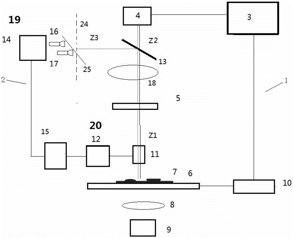
[0064] Combined with accompanying drawings 1 (A), 1 (B), 2 (A), 2 (B).

[0065] A fast digital scanning device for microsections with real-time focusing of the present invention is a scanning device for quickly acquiring all or a considerable part of digital images of microsections, comprising: a digital microscopic imaging system 1 and a The real-time focusing device 2 matched with it. The digital microscopic imaging system 1 includes at least a computer 3, an image detection device 4 connected to the computer to realize photoelectric conversion, and a microscopic optical imaging system 5 between the sample 7 placed on the automatic stage 6 and the image detection device 4 . The microscopic optical imaging system 5 includes at least one objective lens 11 and a matched tube lens 18 , and a filter cube may be placed between the objective lens and the tube lens. The digital micro-imaging system 1 also includes at least an illumination optical system 8 and an illumination light...

Embodiment 2

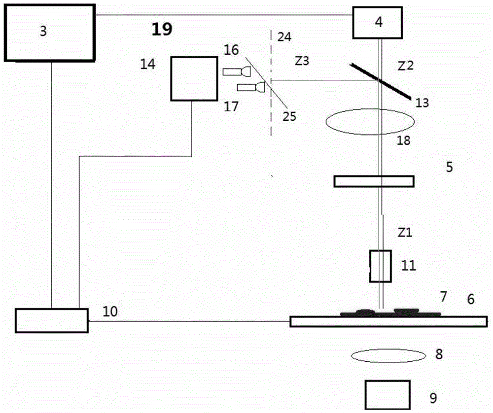
[0078] Combined with accompanying drawings 1 (A), 1 (B), 3 (A), 3 (B).

[0079] Compared with the first embodiment, this embodiment only expands the detection range of the defocus amount of the first embodiment. Therefore, except that a few more optical signal detection elements are placed, the rest of the components are the same, and will not be repeated here, and only the special part of this embodiment, that is, the defocus measurement part, will be described below.

[0080] When the defocus distance 2d that can be effectively measured by a pair of optical signal detection elements along the first straight line cannot meet the requirements, multiple pairs of optical signal detection elements can be placed along the first straight line. Figure 3(A) shows the situation where two pairs of four optical signal detection elements are placed. They are projected on the XY plane along the X direction, and the defocus range of the focal plane that can be measured by the first pair of...

Embodiment 3

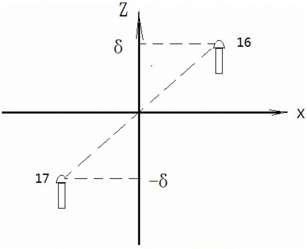
[0087] Compared with the first embodiment, this embodiment is that a pair of optical signal detection elements are placed in the first linear direction, and their projection on the XY plane is along the X direction, and they form an angle α with the XY plane. On this basis, a second pair of optical signal detection elements is placed in the second linear direction, and the angle between them and the XY plane is also α, and the projection of the second pair on the XY plane is parallel to the Y direction. Therefore, compared with Embodiment 1, except that a pair of optical signal detection elements are placed in the Y direction, other components are the same, and will not be described again here.

[0088] In this implementation example, the defocus measurement ranges of the photoelectric conversion in the X / Y direction projected on the XY plane are between [-d, d]. When the defocus measurement device along the X direction measures the defocus amount as x, and the defocus measure...


PUM


Abstract

The invention discloses a microsection fast digital scanning device with real-time focusing and a method thereof. The device comprises a digital microscopic imaging system and a real-time focusing device matched and combined with it. The digital microscope system includes a computer, an image detection device that realizes photoelectric conversion, a microscopic optical imaging system, an automatic stage and a corresponding motion and control system, a microscope illumination optical system, and an illumination source. The real-time focusing device includes a device for measuring the defocus amount of the sample and a device for driving the sample or the objective lens to move and make the focal plane of the sample coincide with the objective lens. The invention can detect the distance between the sample and the focal plane of the imaging system in real time during the slice scanning process and realize real-time focusing, so as to obtain excellent images. The time-consuming focal plane modeling process can be avoided by using the real-time focusing technology; at the same time, a large focusing range and focusing accuracy are taken into account; in addition, the method is not only high in efficiency, but also low in cost.

Description

technical field [0001] The invention belongs to the technical field of microscopes, in particular to a fast digital scanning device for microsections with real-time focusing and a method thereof. Background technique [0002] In teaching, remote pathological diagnosis, software-based intelligent automatic identification system and other applications, it is necessary to provide the whole picture of the tissue sample observed under the microscope for multiple people to read, or to read in different places, or at different times when there is neither actual section nor microscope Next read, diagnose, or permanently save. These applications all require the digitization of the entire or substantial portion of a tissue sample. To meet this demand, the full-slice digital rapid scanning system for microsections, also known as the virtual microscopic imaging system, is a highly integrated device that integrates microscopic optical imaging technology, digital imaging technology, and ...

Claims


Application Information

Patent Timeline
Patent Type & Authority Patents(China)
IPC IPC(8): G02B21/24
Inventor 易定容
Owner MOTIC CHINA GRP CO LTD
Why Eureka
Try Eureka