Battery cooling system of novel energy vehicle

An energy and battery technology, applied in the field of battery cooling of new energy vehicles, can solve problems such as low volumetric efficiency and energy efficiency, poor heat dissipation effect, battery capacity, lifespan and energy efficiency reduction, etc., to ensure consistency and accelerate heat dissipation The effect of dissipating and lowering the temperature

Inactive Publication Date: 2014-06-11
SHANGHAI PUDONG INTPROP PROTECTION ASSOC +1
View PDF0 Cites 40 Cited by
  • Summary
  • Abstract
  • Description
  • Claims
  • Application Information

AI Technical Summary

Problems solved by technology

When the vehicle is running under different driving conditions such as high speed, low speed, acceleration, deceleration, etc., the battery will be discharged at different rates, and a large amount of heat will be generated at different heat generation rates. In addition to time accumulation and spatial influence, uneven heat accumulation will occur , resulting in complex and variable operating temperature of the battery pack
Excessively high temperature will reduce the capacity, life and energy efficiency of the battery. If the heat accumulated in the battery cannot be dissipated in time, it will lead to thermal runaway. In severe cases, the battery may have the risk of violent expansion and explosion
However, the traditional common power battery cooling and heat dissipation devices have many shortcomings such as poor heat dissipation, too much space in the car body, and low volumetric efficiency and energy efficiency.

Method used


Image

  • Battery cooling system of novel energy vehicle
  • Battery cooling system of novel energy vehicle
  • Battery cooling system of novel energy vehicle

Examples


Embodiment Construction

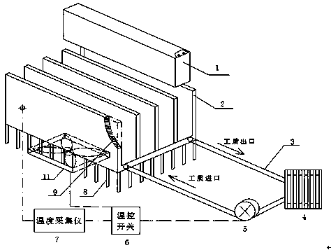
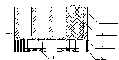
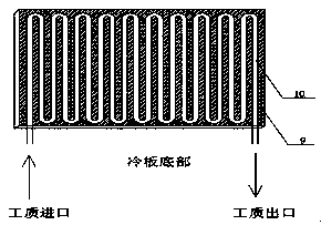
[0016] When the electric vehicle is running, the power battery 1 will be discharged at different discharge rates, which will cause the temperature of the power battery 1 to rise. When the power battery 1 starts to discharge, the heat production is not too large, and the battery temperature will rise slowly. At this time, the temperature control switches 6 and 6' of the system are all disconnected, and the pump 5 and fan 11 of the liquid cooling system are not in operation. The main heat dissipation mode of the power battery 1 is realized through the heat absorption of the phase change material 9 in the housing of the aluminum refrigeration plate 1 and the external heat dissipation of the fins 8 at the bottom of the housing. These two heat dissipation methods can keep the power battery at an appropriate temperature under normal operating conditions and ensure the temperature uniformity of the battery cells. At this time, the system does not need to consume energy, but still has...


PUM

PropertyMeasurementUnit
phase transition temperatureaaaaaaaaaa

Abstract

The invention relates to a battery cooling system of a novel energy vehicle. According to the system, a metal cold plate is adopted for improving the thermal conductivity of a battery pack and a phase change material, and a metal cold plate shell is filled with the phase change material which absorbs heat to keep the temperature of the battery pack in a proper range and ensure the uniform temperature of batteries; a coil pipe type heat dissipater is arranged in the structure and the structure is filled with a liquid cooling medium to take away heat of the batteries, and a fan is arranged outside the structure to increase the heat dissipation speed of the batteries through forced air cooling; four cooling modes are effectively combined to remarkably reduce the temperature of the battery pack and ensure the temperature uniformity of battery monomers; as a temperature control sensor and a switch are designed for temperature control, the battery cooling process can be automatically adjusted and controlled by stages to achieve the purpose of intelligent temperature control.

Description

Technical field [0001] The invention involves a battery cooling system in the field of energy -saving, which is mainly used for battery cooling of new energy vehicles. Background technique [0002] Electric vehicles (EVS for short) use battery as a source of power, can achieve zero pollution in use, and can use other non -oil resources such as coal and hydraulic power to effectively solve the problem of automotive sewage and energy, so it is generally valued worldwide.The performance and quality of these vehicles to a large extent rely on the performance of the power battery packs it configured, especially the reliability, cycle performance and cost of power batteries. [0003] Temperature is a vital factors affecting the performance of power battery.When the vehicle runs under different driving conditions such as high -speed, low -speed, acceleration, deceleration, etc., the battery will discharge at different magnification, generate a lot of heat at different heat rates, plus t...

Claims


Application Information

Patent Timeline
Patent Type & Authority Applications(China)
IPC IPC(8): H01M10/613H01M10/625H01M10/635H01M10/6555H01M10/6552H01M10/6563H01M10/6568
CPCB60L58/26H01M2220/20Y02E60/10Y02T10/70
Inventor 孟繁锟
Owner SHANGHAI PUDONG INTPROP PROTECTION ASSOC
Why Eureka
Try Eureka