Differential capacitance displacement conversion and subdivision method and capacitive linear displacement measuring system

A technology of differential capacitance and displacement, applied in the direction of electric/magnetic position measurement, electromagnetic measuring device, measuring device, etc., which can solve the problems of complicated and limited manufacturing process and large number of electrodes

Active Publication Date: 2014-06-18
王祖斌
View PDF39 Cites 18 Cited by
  • Summary
  • Abstract
  • Description
  • Claims
  • Application Information

AI Technical Summary

Problems solved by technology

[0041] However, in the above-mentioned first method, the absolute displacement measurement is carried out by obtaining analog quantities, which is easily affected by the inclination of the reading unit. The actual installation and movement of the reading unit cannot be completely parallel to the displacement scale unit. The measured value of the displacement will be different due to the inclination of the reading unit, and the anti-interference ability is poor; moreover, each electrode needs to be cut at a specific position, the manufacturing process is complicated and the cost is high
In the second method, due to the need to include multiple electrodes, the number of electrodes is large, the cost is high, and the realization of connecting each electrode to a signal line with a specified polarity is more complicated.
[0042] It is said that in the CN101995208 (or WO2011018497) patent, a comprehensive analysis and comparison of the problems existing in the prior art shows that the problems existing in the modification are still complicated, so the patent CN101995208 (or WO2011018497) has made further improvements ; It is also true that the electrode pattern as stated in the patent is simpler, each electrode does not need to be cut at a specific position, and the manufacturing process is also very simple, but there are two excitation signal sources and a specific rectangular sensing area, etc., each excitation signal source There are four (or more than four) signals with different phases. The incremental displacement measurement mode is to measure the fraction of displacement, which is still a traditional measurement method. The absolute displacement measurement mode has a large displacement range and a specific rectangular sensing area. The number is large, so the displacement measurement range is limited; both the displacement scale unit and the reading unit have multiple external signal lines, so the connection between the moving part and the fixed part is also a troublesome problem
In short, the comparison above shows that the various problems in the existing technology are all caused by the current measurement method, and it is difficult to completely solve them ideally.

Method used


Image

  • Differential capacitance displacement conversion and subdivision method and capacitive linear displacement measuring system
  • Differential capacitance displacement conversion and subdivision method and capacitive linear displacement measuring system
  • Differential capacitance displacement conversion and subdivision method and capacitive linear displacement measuring system

Examples


Embodiment Construction

[0148] In order to make the purpose, technical solution and advantages of the present invention clearer, the present invention will be described in detail with reference to the accompanying drawings and specific embodiments.

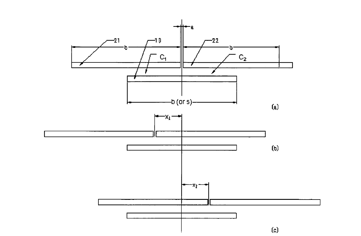
[0149] figure 1 is a schematic diagram of the operation of a capacitive sensor with a pair of differential electrodes. 10 among the figure is the electrode of fixed pole plate. 21 and 22 are the electrodes of the moving plate respectively. The electrode 10 of the fixed plate and the electrodes 21 and 22 of the movable plate are a schematic diagram of a capacitive sensor forming a pair of differential electrodes. b (or s) is the width of the electrode (or the distance s of the differential displacement interval). a is the insulation width of adjacent electrodes. Considering that the electrode width b is greater than the insulation width a of the adjacent electrode, and the value of a is very small, it is ignored. In US3857092 patent figure 1 The i...


PUM


Abstract

The invention relates to a differential capacitance displacement conversion and subdivision method and a capacitive linear displacement measuring system. First, the displacement is solved with the use of a conversion reference of differential capacitance displacement, no modulation, demodulation, amplifier or A / D is needed, and measurement and subdivision are simple and accurate; second, differential capacitance variation is converted into pulse width, a circuit needs no zeroing, no noise, parasitic or zero drift interference exists, and the range is not limited and is only related with the series resistance; third, the capacitive linear displacement measuring system is provided by the use of the method and the circuit, the system is large in range and can be used for performing absolute position measurement, a sensor and a circuit of the system are simple, and the system is fully digital, high in precision and good in stability, can be used in harsh environments with water, oil or dust pollution and is better than an optical grating, a ball grid or the like; and fourth, the sensor, the circuit, a display and the like are integrated into a micro (MEMS) device, the precision is at the nanometer level, motion parameters of the MEMS such as mechanical position, displacement, velocity, amplitude and frequency can be accurately measured, and parameter transformation is remotely controlled.

Description

technical field [0001] The invention relates to capacitance displacement measurement technology, in particular to a conversion and subdivision method of differential capacitance displacement and a capacitance type linear displacement measurement system. The conversion of the said differential capacitance displacement has two purposes, the first purpose is to propose the conversion benchmark of the differential capacitance displacement, and the second purpose is to convert the differential capacitance change into a pulse width quantity; this capacitive linear displacement measurement The system is an all-digital type with large range, absolute position measurement, sensor production and simple circuit, and can be used in harsh environments such as water, oil, and dust pollution; there is also miniaturization (MEMS), and the accuracy is nanometer. Background technique [0002] The capacitive sensor started early. In 1920, Wellington manufactured a capacitive micrometer, which ...

Claims


Application Information

Patent Timeline
Patent Type & Authority Applications(China)
IPC IPC(8): G01B7/02G01B7/00G01D5/241H03K17/945
CPCG01B7/003G01D5/12G01B7/00G01R27/26G01D5/2412
Inventor 王祖斌
Owner 王祖斌
Why Eureka
Try Eureka