Planar structured light three dimension measuring device and method for high-reflectivity part

A technology of surface structured light and three-dimensional measurement, applied in the direction of measuring devices, optical devices, instruments, etc., can solve the problems of slow measurement speed, complex structure, large volume, etc., and achieve high measurement efficiency, small size, and high projection frequency Effect

Active Publication Date: 2014-06-18
南京禺疆电子技术有限公司
View PDF7 Cites 34 Cited by
  • Summary
  • Abstract
  • Description
  • Claims
  • Application Information

AI Technical Summary

Problems solved by technology

[0009] The purpose of the present invention is to solve the problems of large volume and slow measurement speed due to the complex structure o...

Method used


Image

  • Planar structured light three dimension measuring device and method for high-reflectivity part
  • Planar structured light three dimension measuring device and method for high-reflectivity part
  • Planar structured light three dimension measuring device and method for high-reflectivity part

Examples


specific Embodiment approach 1

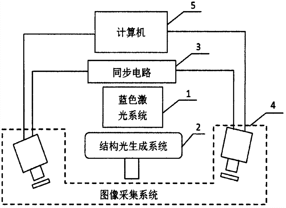
[0042] Specific implementation mode 1. Combination figure 1 Describe this specific embodiment, a surface structured light three-dimensional measurement device for high reflectivity parts, which includes a blue laser system (1), a structured light generation system (2), a synchronization circuit (3), an image acquisition system ( 4) and computer (5);

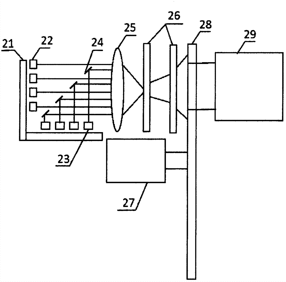
[0043] The blue laser system (1) comprises a laser diode driving circuit (21), a blue laser module No. 1 (22), a blue laser module No. 2 (23), a mirror (24), a converging lens (25) and Diffusion sheet group (26);

[0044] The structured light generation system (2) includes a servo motor (27), a circular grating sheet with a pattern (28) and a focusing lens (29);

[0045] The No. 1 blue laser module (22) is vertically set, and the No. 2 blue laser module (23) is horizontally set;

[0046] The light in the horizontal direction emitted by the blue laser system (1) through the No. 1 blue laser module (22) is incident on the conver...

specific Embodiment approach 2

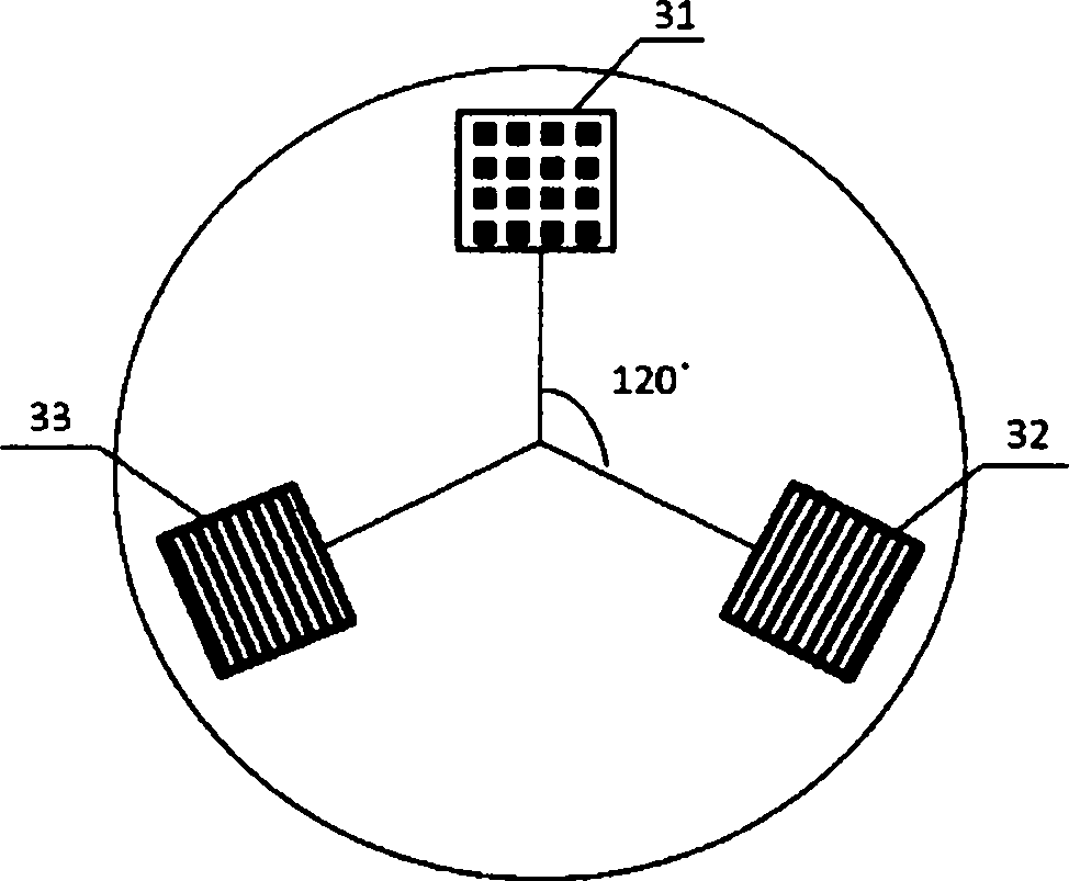
[0052] Embodiment 2. The difference between this embodiment and the surface structured light three-dimensional measurement device for high-reflectivity parts described in Embodiment 1 is that the circular grating sheet (28) with a pattern has three The first pattern is a two-dimensional random coding pattern or a two-dimensional pseudo-random coding pattern; the second pattern is a stripe pattern composed of periodic black and white stripes; the third pattern is a mirror image pattern of the second pattern.

specific Embodiment approach 3

[0053] Specific Embodiment 3. The difference between this specific embodiment and the surface structured light three-dimensional measuring device for high-reflectivity parts described in specific embodiment 2 is that the three The patterns are evenly distributed on the circumference of the circular lenticular sheet.


PUM


Abstract

A planar structured light three dimension measuring device and method for a high-reflectivity part relate to the field of three dimension optical measurement and aim to solve the problems of large size and slow measuring speed due to the complex structure of the existing device. The planar structured light three dimension measuring device comprises a blue laser source system, a structured light pattern generation system, a synchronous control circuit, an image collection system and a computer. The device has the advantages of small size, light weight, fast projecting speed and the like. The phenomena of local mirror reflection, mutual reflection and direction reflection and the like at the part surface are effectively inhibited by the projecting random or pseudo random coding patterns and two groups of periodically, forwardly and reversely changed black and white strip patterns, the sub pixel point match of two images shot by left and right cameras are fast realized, and the efficient measurement of the high-reflectivity part is finished. The planar structured light three dimension measuring device and method for the high-reflectivity part is suitable for the planar structured light three dimension measurement of the high-reflectivity part.

Description

technical field [0001] The invention relates to the field of three-dimensional optical measurement, in particular to a device and method for realizing uncoated optical three-dimensional measurement by applying surface structured light to metal and non-metal parts with specular reflection and directional reflection on the surface. Background technique [0002] With the rapid development of computer and electronic information technology, the three-dimensional measurement technology of surface structured light is becoming more and more mature. Because the surface structured light measurement technology has the characteristics of non-contact, fast measurement speed and high precision. At present, it has been widely used in product quality inspection, reverse engineering and other fields. However, when measuring the finished metal primary color surface parts, when the surface structured light is projected onto the part surface, the local specular reflection and mutual reflection...

Claims


Application Information

Patent Timeline
IPC IPC(8): G01B11/25
Inventor 何万涛郭延艳车向前马鹤瑶孟祥林刘丹丹赵灿程俊廷
Owner 南京禺疆电子技术有限公司
Why Eureka
Try Eureka