Method for machining high-strength steel hot stamping formed parts

A hot stamping forming and part processing technology is applied in the processing field of realizing the above-mentioned parts trimming and punching and collision energy absorption area, which can solve the problems of low production efficiency, high investment cost and high strength, so as to reduce production difficulty and improve collision performance, the effect of improving production efficiency

Active Publication Date: 2014-06-25
吉林省正轩车架有限公司
View PDF5 Cites 28 Cited by
  • Summary
  • Abstract
  • Description
  • Claims
  • Application Information

AI Technical Summary

Problems solved by technology

Due to the high strength (1500-1700MPa) of hot stamping parts of high-strength steel plates, conventional punching and trimming technology is difficult to achieve, and only laser cutting technology can be used
Although the processing cost has decreased with the maturity of laser cutting equipment and technology, it is still difficult to achieve beat synchronization with the existing thermoforming process, so multiple sets of 3D laser cutting equipment are needed to achieve synchronization with the thermoforming production line
The low production efficiency and high investment...

Method used


Image

  • Method for machining high-strength steel hot stamping formed parts
  • Method for machining high-strength steel hot stamping formed parts
  • Method for machining high-strength steel hot stamping formed parts

Examples


Embodiment Construction

[0017] Below in conjunction with specific embodiment and accompanying drawing, the present invention is described in further detail:

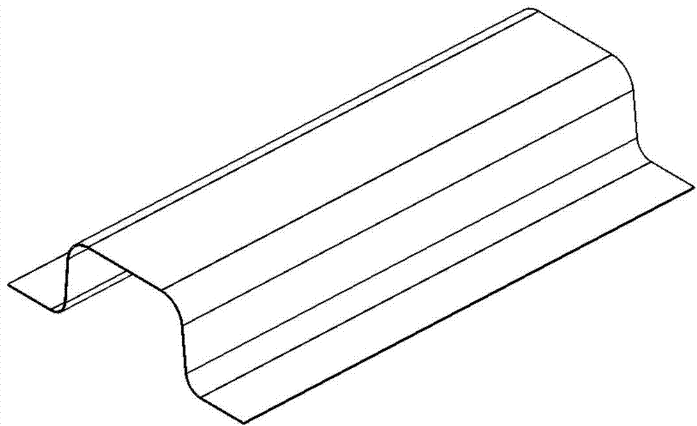
[0018] figure 1 It is a part after hot stamping forming, and the overall performance is uniform, and the performance is: strength 1500MPa, shaping 5%. need according to figure 2 The performance requirements are changed to improve the collision performance and cutting edge punching performance by changing the local strong shaping.

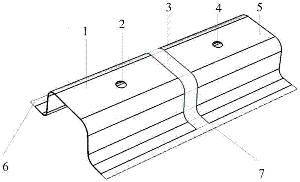
[0019] According to the three-dimensional structure and performance requirements of parts, such as figure 2 , such as according to the local needs of trimming punching and performance requirements of energy-absorbing parts, determine the gradient distribution state of part performance. figure 2 In the figure, the performance requirements of part 1 in the left half are: strength 1500MPa, elongation 5%; the performance requirements of impact energy-absorbing area 5 in the right half part are: strength 600MPa, elo...


PUM


Abstract

The invention discloses a method for machining high-strength steel hot stamping formed parts. The main principle of the machining method is that partial tempering or annealing processing is carried out on the hot stamping formed parts with the uniform performance, gradient changes of the tempering or annealing temperature are achieved through heat conduction of a board, gradient changes of the performance are achieved, and the partial trimming and hole punching performance and the impact performance of the parts are improved on the premise that the high strength is kept on other portions. The method includes the implementation steps of according to three-dimensional structures of a trimming and hole punching region and an impact energy absorption region, designing corresponding high-frequency induction heating coils, partially tempering or annealing the trimming and hole punching region and the impact energy absorption region to enable the trimming and hole punching region and the impact energy absorption region to be at certain temperature, achieving the gradient changes of the tempering or annealing temperature, carrying out air cooling on the partially-tempered or partially-annealed parts to enable the partially-tempered or partially-annealed parts to be at certain temperature, and finally and rapidly moving the air-cooled hot stamping formed parts to a trimming and hole punching mold to carry out mold trimming and hole punching.

Description

technical field [0001] The invention belongs to the field of processing high-strength steel hot stamping formed parts, and more specifically relates to a method for realizing the processing of the part trimming and punching and the collision energy-absorbing area. Background technique [0002] High-strength steel hot-formed parts can reach a high strength of 1500-1700MPa, but its ductility will decrease with the increase of strength, and some parts of the passenger car body need to have a certain strength and plasticity to absorb energy to improve Crashworthiness. For example, the B-pillar of the car body needs sufficient strength for the upper part and the middle part so that the car can ensure the integrity of the car body when it is under impact, and prevent collisions and intrusions from causing occupant damage. In addition to the need for a certain strength, the lower part needs better strength Ductility to absorb impact energy. [0003] In the existing high-strength ...

Claims


Application Information

Patent Timeline
IPC IPC(8): B21D35/00C21D8/00C21D1/42
CPCY02P10/25
Inventor 张宜生刘培星王凯徐亚
Owner 吉林省正轩车架有限公司
Why Eureka
Try Eureka