Design method for vertical constant force system

A vertical direction and system design technology, applied in space navigation equipment, simulation devices of space navigation conditions, transportation and packaging, etc., can solve problems such as failure, small range of motion, and high accuracy requirements of spring coefficients, and achieve cost and maintenance costs The effect of low, increased degree of freedom, and easy operation

Active Publication Date: 2014-06-25
BEIHANG UNIV
View PDF3 Cites 25 Cited by
  • Summary
  • Abstract
  • Description
  • Claims
  • Application Information

AI Technical Summary

Problems solved by technology

The patent application number is CN201220400797 "Semi-active gravity compensation structure air bearing six degrees of freedom analog satellite device" announced a "parallel connection" scheme through the integration of motor ball screw and cylinder suspension to compensate the gravity of the spacecraft and Provides the freedom of movement in the vertical direction, which solves the problem that the air flotation method can only perform five-degree-of-freedom movement simulation, but its structure is relatively complicated, the air compression processing equipment occupies a large area, and the cost of marble is expensive; the patent application number is CN201310466806 "A Design Method for Unconstrained Suspension Active Gravity Compensation System" published a method to compensate the gravity of the spacecraft through hanging wire tension suspension to provide the freedom of movement in the vertical direction, but when the momentary force on the spacecraft exceeds the gravity of the spacecraft, The tension on the hanging wire changes suddenly, wh

Method used


Image

  • Design method for vertical constant force system
  • Design method for vertical constant force system
  • Design method for vertical constant force system

Examples


Embodiment Construction

[0031] The present invention will be further described below in conjunction with the accompanying drawings.

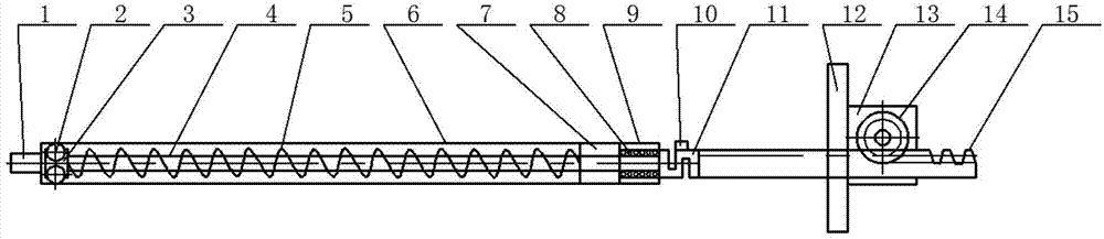
[0032] combine figure 1 and Figure 5, the basic idea of ​​the present invention is to use the feedforward information of the spacecraft to realize the system constant force output near the balance point through the balance point constant force spring module. When there is a force in the vertical direction to make it deviate from the balance point, the tension sensor and The change measured by the displacement sensor is transmitted to the PC. After the PC processes the signal, it issues a control command to control the movement of the rack and pinion compensation module to compensate for the change of the force on the spring caused by the external force and ensure the constant force output of the system.

[0033] The left end of the connecting end 1 of the spring jacket can be connected with the spacecraft or the device for suspending the spacecraft, and the other end...


PUM


Abstract

The invention provides a design method for a vertical constant force system. The vertical constant force system comprises a balance point constant force spring module, a gear and rack compensation module and a data acquisition and control module and is used for compensating the gravity generated in the process of ground validation of a spacecraft. The balance point constant force spring module comprises a compressed spring, a linear guide rail, linear bearings, rolling bearings, a spring jacket and connecting parts and is used for providing constant force at a balance point. The gear and rack compensation module comprises a gear and rack set, a motor and a fixing plate. When the spacecraft deviates from the balance point, the gear and rack compensation module can drive the balance point constant force spring module arranged at the lower end of the gear and rack compensation module to do acceleration and deceleration motion or uniform motion in the vertical direction to adjust force on the compressed spring, so constant force output is guaranteed. The data acquisition and control module comprises a motor driver, a control card, a high-precision tension sensor, a displacement sensor, a data acquisition card and an upper computer PC. The vertical constant force system can be used for providing the constant force in the vertical direction and compensating the gravity of the spacecraft and has the advantages being stable in operation, not prone to external interference, high in constant force accuracy and the like.

Description

Technical field [0001] The invention belongs to the technical field of ground verification of spacecraft navigation, guidance and control systems, and in particular relates to a method for realizing a vertical constant force system. Background technique [0002] Aerospace engineering is a high-risk, high-investment, high-reward, highly complex and high-precision system engineering. Its development level determines whether it can seize the high-tech commanding heights and maximize the use of space resources. There is no doubt that it is imminent to actively carry out aerospace technology research in our country. However, the space environment is extremely harsh. In order to successfully complete space missions, sufficient experiments must be carried out on the ground. Therefore, various space agencies at home and abroad attach great importance to the experimental verification of spacecraft on the ground. [0003] One of the most important features of the space environment is ...

Claims


Application Information

Patent Timeline
IPC IPC(8): B64G7/00
Inventor 贾英民孙施浩贾娇
Owner BEIHANG UNIV
Why Eureka
Try Eureka