Light-splitting pupil laser differential motion confocal Brillouin-Raman spectrum measurement method and device

A Raman spectroscopy, differential confocal technology, applied in measurement devices, Raman/scattering spectroscopy, optical radiation measurement, etc., can solve the problems of abandonment, affecting the signal-to-noise ratio and limitation of Raman spectroscopy detection instruments

Active Publication Date: 2014-06-25
BEIJING INSTITUTE OF TECHNOLOGYGY
View PDF7 Cites 30 Cited by
  • Summary
  • Abstract
  • Description
  • Claims
  • Application Information

AI Technical Summary

Problems solved by technology

[0009] (1) The spatial resolution is not high, only about 1 μm
The intensity signal of the Raman spectrum excited by the laser is very weak, which is about 6 orders of magnitude lower than the intensity of the abandoned sharp beam. Therefore, in order to detect the extremely weak Raman signal, the aperture of the pinhole of the confocal Raman spectroscopy detection system is usually exist It is about 10 μm larger than the pinhole aperture value of the existing confocal microscope. As a result, the spatial resolution of the existing confocal Raman spectrum is only 1 μm, and since the confocal Raman spectrum detection technology was invented more than 20 years ago has not fundamentally changed
[0010] (2) Poor ability to capture the Raman spectrum excited by the focal point
Confocal Raman spectroscopy detection system, due to the insensitive intensity response at the extreme point, it is difficult to capture the Raman spectrum information of the sample excited at the focal point, thus limiting the spatial resolution of the existing confocal Raman spectroscopy detection ability;
[0011] (3) Long detection time and large system drift
Because the confocal Raman spectrum signal is very weak, the detector needs to be integrated for a long time (often several hours) when performing spectral imaging. The drift of the optical system and the sample worktable often causes the sample to defocus, which in turn reduces the confocal Raman. Spatial resolution of spectral detection;
[0012] (4) The stray light of the sample is strong, which affects the signal-to-noise ratio of the Ra

Method used


Image

  • Light-splitting pupil laser differential motion confocal Brillouin-Raman spectrum measurement method and device
  • Light-splitting pupil laser differential motion confocal Brillouin-Raman spectrum measurement method and device
  • Light-splitting pupil laser differential motion confocal Brillouin-Raman spectrum measurement method and device

Examples


Embodiment 1

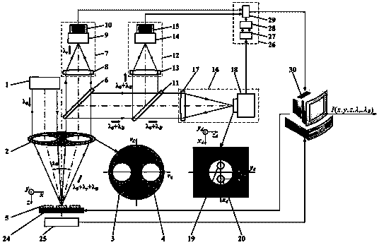
[0072] The split-pupil laser differential confocal Brillouin-Raman spectroscopy measurement method comprises the following steps:

[0073] Such as image 3 As shown, first, the illumination pupil 3 and the collection pupil 4 are placed on the pupil plane of the measurement objective lens 2; the light source system 1 emits an excitation beam, and after the excitation beam passes through the illumination pupil 3 of the measurement objective lens 2, it is focused on the measured On sample 5, the Raman scattered light and Brillouin scattered light carrying the spectral characteristics of the measured sample 5 are excited, and Rayleigh light is reflected; the Raman scattered light, Brillouin scattered light and Rayleigh light are collected by the measuring objective lens 2 The pupil 4 reaches the dichroic spectroscopic system 6; the dichroic spectroscopic system 6 performs lossless separation of the Raman scattered light from other spectra; the Brillouin scattered light and Rayleig...

Embodiment 2

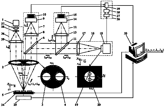
[0091] In this embodiment, the dichroic spectroscopic system 6 is a Notch Filter, the first spectral detector 9 is a Raman spectroscopic detector, the spectroscopic system 11 is a spectroscope, and the second spectroscopic detector 14 is a Brillouin spectroscopic detector. The acquisition system 18 is a CCD, the 3D scanning system 24 is a 3D scanning workbench, and the image magnification system 47 is a magnifying objective lens.

[0092] Such as Figure 11 As shown, the super-resolution split-pupil laser differential confocal multi-spectral comprehensive test method, the test steps are as follows:

[0093] First, the illumination pupil 3 and the collection pupil 4 are placed on the pupil plane of the measurement objective 2 . The light source system 1 composed of lasers emits excitation light that can excite the Raman spectrum of the sample 5 to be tested. The excitation light is converged by the fourth condenser lens 37 and then enters the third pinhole 38 to become a point...


PUM


Abstract

The invention relates to a light-splitting pupil laser differential motion confocal Brillouin-Raman spectrum measurement method and device and belongs to the technical field of microscopic spectrum imaging. According to the method and the device, the high-resolution imaging of a three-dimensional geometric position of a sample is realized by constructing a light-splitting pupil confocal microscopic imaging system through using rayleigh scattering light abandoned in the confocal Raman spectrum detection; a zero crossing point of a light-splitting pupil laser differential motion confocal microscopic imaging device and a focal point of the zero crossing point are used for corresponding to the property to control a spectrum detector to accurately capture Raman spectrum information excited by a focus point of an objective lens so as to further realize the high-precision detection, namely image and spectrum combined high-space resolution detection on a microcell geometric position and spectrum information of a sample; meanwhile, the resolution capability and a measuring range are considered effectively; the characteristics of complementary advantages of a confocal Raman spectrum detection technology and a confocal Brillouin spectrum detection technology are utilized to design a confocal spectrum detection scheme for detecting by adopting a Raman spectrum and a Brillouin spectrum so as to realize the comprehensive measurement and de-coupling of multi-performance parameters of materials.

Description

technical field [0001] The invention belongs to the technical field of microspectral imaging, and relates to a method and device for measuring a split-pupil laser differential confocal Brillouin-Raman spectrum. The differential confocal microscopic technique is combined with the spectral detection technique to form a "spectrogram" The "integrated" high-resolution spectral imaging and detection method and device can be used for micro-area multispectral, multi-performance parameter comprehensive testing and high-resolution imaging of samples. Background technique [0002] The phenomenon of light emission widely exists in the interaction process between light and particles, that is, when a beam of light passes through a medium, the medium particles are affected by the light wave, transition from one quantum state to another quantum state, and radiate scattered waves at the same time, different The way of energy level transition produces Rayleigh, anti-Stokes and Stokes scatteri...

Claims


Application Information

Patent Timeline
IPC IPC(8): G01N21/65G01N21/01
CPCG01J3/0208G01J3/0229G01J3/4412G01N21/65G01N2021/638G02B21/0032G02B21/0076
Inventor 赵维谦盛忠邱丽荣王允
Owner BEIJING INSTITUTE OF TECHNOLOGYGY
Why Eureka
Try Eureka