Laser multi-beam combining device and method thereof

A laser and multi-beam technology, which is applied in the direction of laser devices, semiconductor laser devices, devices for controlling laser output parameters, etc., can solve problems such as failure to meet etiology inspection requirements, poor temperature reliability, and poor beam combining accuracy, etc., to reduce errors The probability of judgment, small size, and the effect of improving polarization characteristics

Inactive Publication Date: 2014-06-25
PAVILION INTEGRATION CORP SUZHOU
View PDF6 Cites 14 Cited by
  • Summary
  • Abstract
  • Description
  • Claims
  • Application Information

AI Technical Summary

Problems solved by technology

The currently used instruments generally use two beams of light in free space to couple through a mirror, which has disadvantages such as poor beam combining accuracy, poor temperature reliability, and large background noise, which cannot meet the inspection requirements for etiology.

Method used


Image

  • Laser multi-beam combining device and method thereof
  • Laser multi-beam combining device and method thereof
  • Laser multi-beam combining device and method thereof

Examples


Embodiment 1

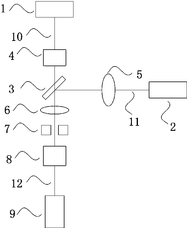
[0029] A multi-beam laser beam combining device of this embodiment, such as figure 1 As shown, a first laser 1 and a second laser 2 are included. Optionally, the first laser 1 and the second laser 2 are frequency-doubled lasers or semiconductor lasers respectively. Also includes a dichroic mirror 3, the first laser 1 is arranged on the transmission light path of the dichroic mirror 3, the second laser 2 is arranged on the reflection light path of the dichroic mirror 3, the first laser 1 and the dichroic mirror 3 is provided with a coupling mirror 4 for collimating the spot size, and a collimating mirror 5 for collimating the spot size is provided between the second laser 2 and the dichroic mirror 3 . The light emitted by the first laser 1 and the second laser 2 is respectively transmitted and reflected by the dichroic mirror 3 and recombined into an output optical path. An achromatic lens 6, an aperture stop 7, and a beam combiner 8 are arranged in sequence on the output optic...

Embodiment 2

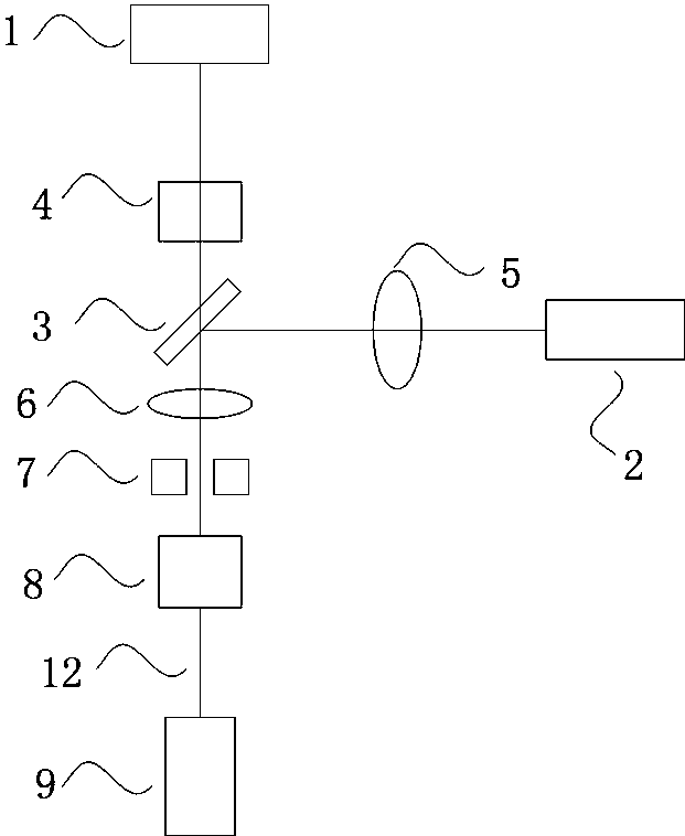
[0035] A multi-beam laser beam combining device of this embodiment, such as figure 2As shown, a first laser 1 and a second laser 2 are included. Optionally, the first laser 1 and the second laser 2 are frequency-doubled lasers or semiconductor lasers respectively. Also includes a dichroic mirror 3, the first laser 1 is arranged on the transmission light path of the dichroic mirror 3, the second laser 2 is arranged on the reflection light path of the dichroic mirror 3, the first laser 1 and the dichroic mirror 3 is provided with a coupling mirror 4 for collimating the spot size, and a collimating mirror 5 for collimating the spot size is provided between the second laser 2 and the dichroic mirror 3 . The light emitted by the first laser 1 and the second laser 2 is respectively transmitted and reflected by the dichroic mirror 3 and recombined into an output optical path. An achromatic lens 6, an aperture stop 7, and a beam combiner 8 are arranged in sequence on the output optic...

Embodiment 3

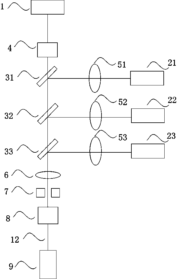
[0041] A multi-beam laser beam combining device of this embodiment, such as image 3 As shown, a first laser 1 and three second lasers 21, 22 and 23 are included. Optionally, the first laser 1 and the second lasers 21, 22 and 23 are frequency-doubled lasers or semiconductor lasers, respectively. Also include three dichroic mirrors 31, 32 and 33 corresponding to the second lasers 21, 22 and 23, the first laser 1 is arranged on the transmission light path of the dichroic mirrors 31, 32 and 33, the second laser 21 is arranged on the reflected optical path of dichroic mirror 31, the second laser 22 is arranged on the reflected optical path of dichroic mirror 32, the second laser 23 is arranged on the reflected optical path of dichroic mirror 33, the first laser 1 and A coupling mirror 4 for collimating the spot size is provided between the dichroic mirrors 31, a collimating mirror 51 for collimating the spot size is provided between the second laser 21 and the dichroic mirror 31,...


PUM

PropertyMeasurementUnit
Thicknessaaaaaaaaaa
Thicknessaaaaaaaaaa

Abstract

The invention discloses a laser multi-beam combining device. The laser multi-beam combining device comprises a first laser, at least one second laser and dichroscopes, wherein the number of the dichroscopes is matched with the number of the second lasers. The first laser is arranged on transmission light paths of all the dichroscopes, each second laser is arranged on a reflected light path of one dichroscope corresponding to the second laser, and light rays emitted out from the first laser and the second lasers are transmitted and reflected by the dichroscopes respectively and then coincide to form an output light path. The output light path is sequentially provided with an achromatic lens, a pinhole diaphragm, a beam combining mirror and a collimator. By means of the laser multi-beam combining device, light rays with two or more wave lengths are combined in a high precision mode, spatial filtering is achieved, beam quality is improved, meanwhile, the implementation size is small, and performance is stable.

Description

technical field [0001] The invention belongs to the technical field of semiconductor lasers, and in particular relates to a multi-beam laser beam combining device and a method thereof. Background technique [0002] Optoelectronic imaging technology is an important part of the field of ophthalmology and optometry research. It is of great significance. It plays an important role in helping clinical ophthalmologists to diagnose and treat ophthalmic diseases, improving the level of ophthalmic medical care, and researchers obtaining images of the surface or internal biological tissues of the human eye. important role, greatly promoting the development of optometry. In the past ten years, the technical research related to wavefront aberration measurement and correction and the development of optoelectronic imaging instruments have attracted widespread attention. The combination of adaptive optics technology with optical coherence tomography and confocal scanning laser ophthalmosco...

Claims


Application Information

Patent Timeline
IPC IPC(8): H01S5/40H01S5/06G02B27/10
Inventor 宫广彪季朝华罗宁一
Owner PAVILION INTEGRATION CORP SUZHOU
Why Eureka
Try Eureka