Dual-fuel nozzle for plasma and gas-assisted atomization burning

A gas-assisted, dual-fuel technology, applied in combustion chambers, combustion methods, combustion equipment, etc., can solve the problems of poor atomization effect of liquid fuel, low combustion efficiency, incomplete fuel combustion, etc., to ensure stability and completeness , Improve the speed of flame propagation, reduce the effect of emission

Inactive Publication Date: 2014-07-02
HARBIN ENG UNIV
View PDF4 Cites 20 Cited by
  • Summary
  • Abstract
  • Description
  • Claims
  • Application Information

AI Technical Summary

Problems solved by technology

[0004] The traditional dual-fuel nozzle has poor atomization effect of the liquid fuel in the oil circuit after passing through the nozzle, and poor swirling effect of the gaseous fuel in the gas path through the...

Method used


Image

  • Dual-fuel nozzle for plasma and gas-assisted atomization burning
  • Dual-fuel nozzle for plasma and gas-assisted atomization burning
  • Dual-fuel nozzle for plasma and gas-assisted atomization burning

Examples


Embodiment Construction

[0017] The present invention is described in more detail below in conjunction with accompanying drawing example:

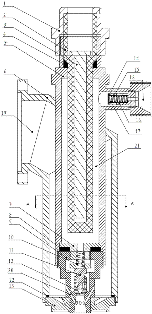
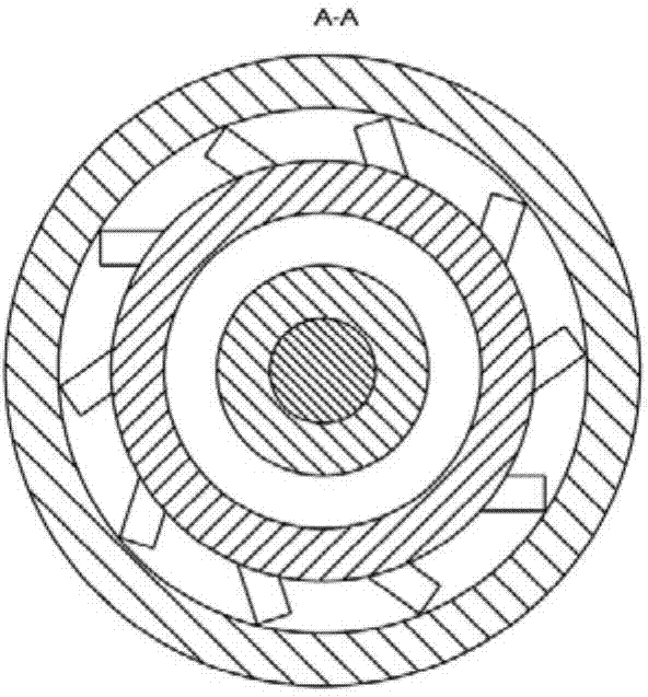
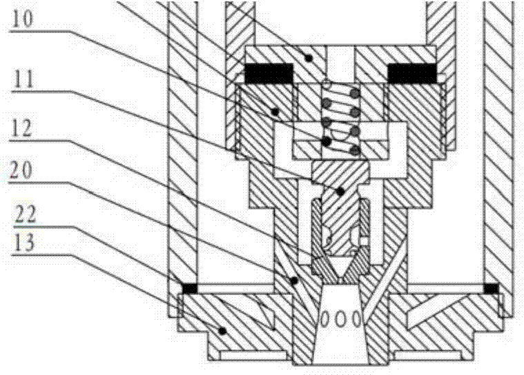
[0018] combine Figure 1~5 , the low-temperature plasma component is connected to the dual-fuel nozzle of plasma and gas-assisted atomization combustion through the external thread of the power connection nut 1 to provide the high voltage required for dielectric barrier discharge, wherein the inner electrode 3 is connected to the high-voltage end, and the outer electrode 5 is connected to zero. The liquid fuel enters the fuel filter assembly composed of the oil baffle plate 14, the oil strainer 15, the oil filter housing 16 and the support spring 17 through welding with the liquid fuel inlet joint 18 on the outer electrode 5, and after filtering Radial into the annular discharge gap 21, the liquid fuel is partially cracked under high voltage to form plasma active micelles, which are contained in the liquid fuel and flow into the swirler bracket 7, sealing gasket 8...


PUM


Abstract

The invention provides a dual-fuel nozzle for plasma and gas-assisted atomization burning. The dual-fuel nozzle for plasma and gas-assisted atomization burning comprises a gas circuit assembly, a plasma discharging assembly, an oil filtering assembly and a gas-assisted swirl nozzle assembly. Liquid fuel passes through the oil filtering assembly and then enters an annular discharging gap of the plasma discharging assembly in the radial direction, the fuel is partially cracked through dielectric barrier discharging to form a plasma micelle which is mixed into the fuel, and instant bursting and inflammability of the plasma micelle at an outlet of the dual-fuel nozzle are utilized for strengthening atomization; one part of gaseous fuel enters the gas-assisted swirl nozzle assembly from an inlet through an annular gas cavity surrounding an external electrode so as to conduct impact assisted atomization on the liquid fuel, and the other part of the gaseous fuel flows out in a rotating mode through a gas flow guiding plate so as to achieve the shearing action on the liquid fuel, so that liquid drops are atomized deeply. According to the dual-fuel nozzle for plasma and gas-assisted atomization burning, deep fuel atomization and stable flow rotation can be well achieved, stability and completeness of burning are improved, and pollutant emission is reduced.

Description

technical field [0001] The invention relates to a gas turbine, in particular to a nozzle mechanism of the gas turbine. Background technique [0002] 1. Dielectric barrier discharge technology: Dielectric barrier discharge technology is a kind of low-temperature plasma catalysis. It is currently mainly used in technical fields such as ozone production, waste gas treatment, material surface modification, and gaseous pollutant treatment. Low temperature plasma catalysis is an extremely effective way to realize low energy consumption, high yield and high selectivity in plasma chemical reaction process. Dielectric barrier discharge technology is mostly used in the research and treatment of gaseous substances, but less research is done on the catalysis of liquid substances. [0003] 2. Dual-fuel gas turbine technology: Gas turbine is a typical conventional fuel power plant. It has the characteristics of small size, high power, light weight and fast start-up, and is widely used i...

Claims


Application Information

Patent Timeline
IPC IPC(8): F23R3/40F23R3/36F23R3/38
Inventor 郑洪涛刘潇齐秀龙邓博阳李智明杨仁杨洪磊
Owner HARBIN ENG UNIV
Why Eureka
Try Eureka