Automatic device for welding and detecting lithium battery

An automatic equipment and lithium battery technology, which is applied in battery assembly machines, secondary battery manufacturing, non-aqueous electrolyte storage batteries, etc., can solve the problems of high labor intensity, reduced production efficiency, and low product quality, and achieve full utilization of the machine Space, space cost savings, and the effect of shortening the running distance

Active Publication Date: 2014-07-02
DONGGUAN HONBRO LI BATTERY EQUIP TECH
4 Cites 31 Cited by

AI-Extracted Technical Summary

Problems solved by technology

[0005] The present invention aims at the deficiencies in the prior art, and its main purpose is to provide an automatic equipment for lithium battery welding and detection, which s...

Method used

Shown in conjunction with Fig. 3, transmission system 1 includes transmission frame 12, conveyor belt 13 and transmission guide groove 14, and this transmission guide groove 14 is arranged on conveyor belt 13 tops, and the both sides inner wa...

Abstract

The invention discloses an automatic device for welding and detecting a lithium battery. The automatic device comprises a transfer system, a temporary storage system, a welding system and a detecting system, wherein the transfer system comprises a transfer stander, a transfer belt and a transfer groove, the temporary storage system comprises a temporary loading-unloading station and a temporary storage loading-unloading mechanical hand, the welding system comprises a welding loading-unloading mechanical hand, a first welding rotating device, a second welding rotating device, a welding head mechanical hand and a welding control box, and the detecting system comprises a detection loading mechanical hand, a loading workstation, a leakage detector, a short-circuit detector, a laser labeling device, an unloading workstation and a detection unloading mechanical hand. The automatic device is compact in structure, reasonable in layout and low in space cost; a battery product is loaded onto the welding system to be welded from the transfer belt, labeled by the detecting system and unloaded through the transfer belt, full automation in control is realized, the labor intensity of workers can be alleviated, and the product quality and production efficiency can be improved.

Application Domain

Assembling battery machinesFinal product manufacture +1

Technology Topic

Transfer systemManipulator +8

Image

  • Automatic device for welding and detecting lithium battery
  • Automatic device for welding and detecting lithium battery
  • Automatic device for welding and detecting lithium battery

Examples

  • Experimental program(1)

Example Embodiment

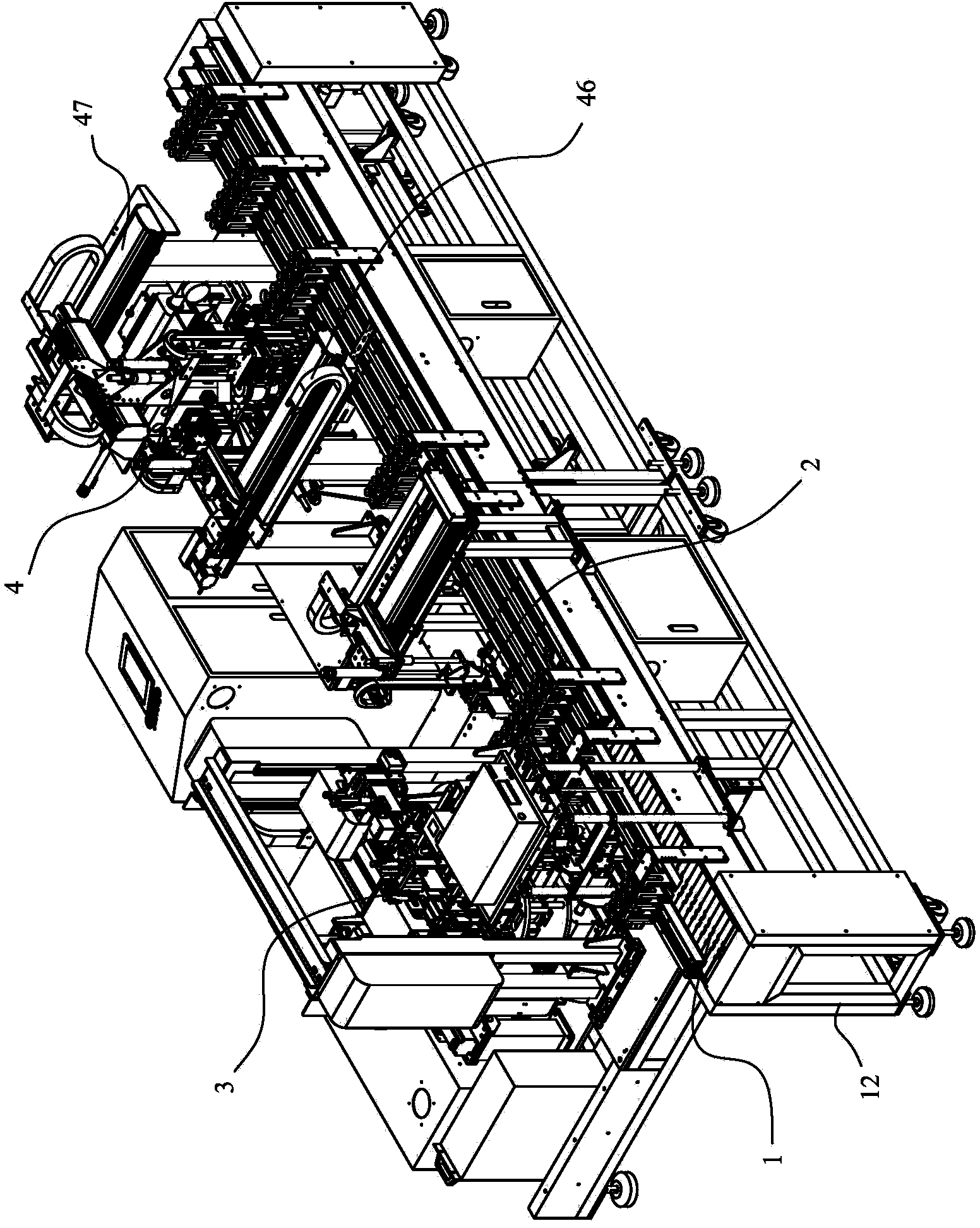
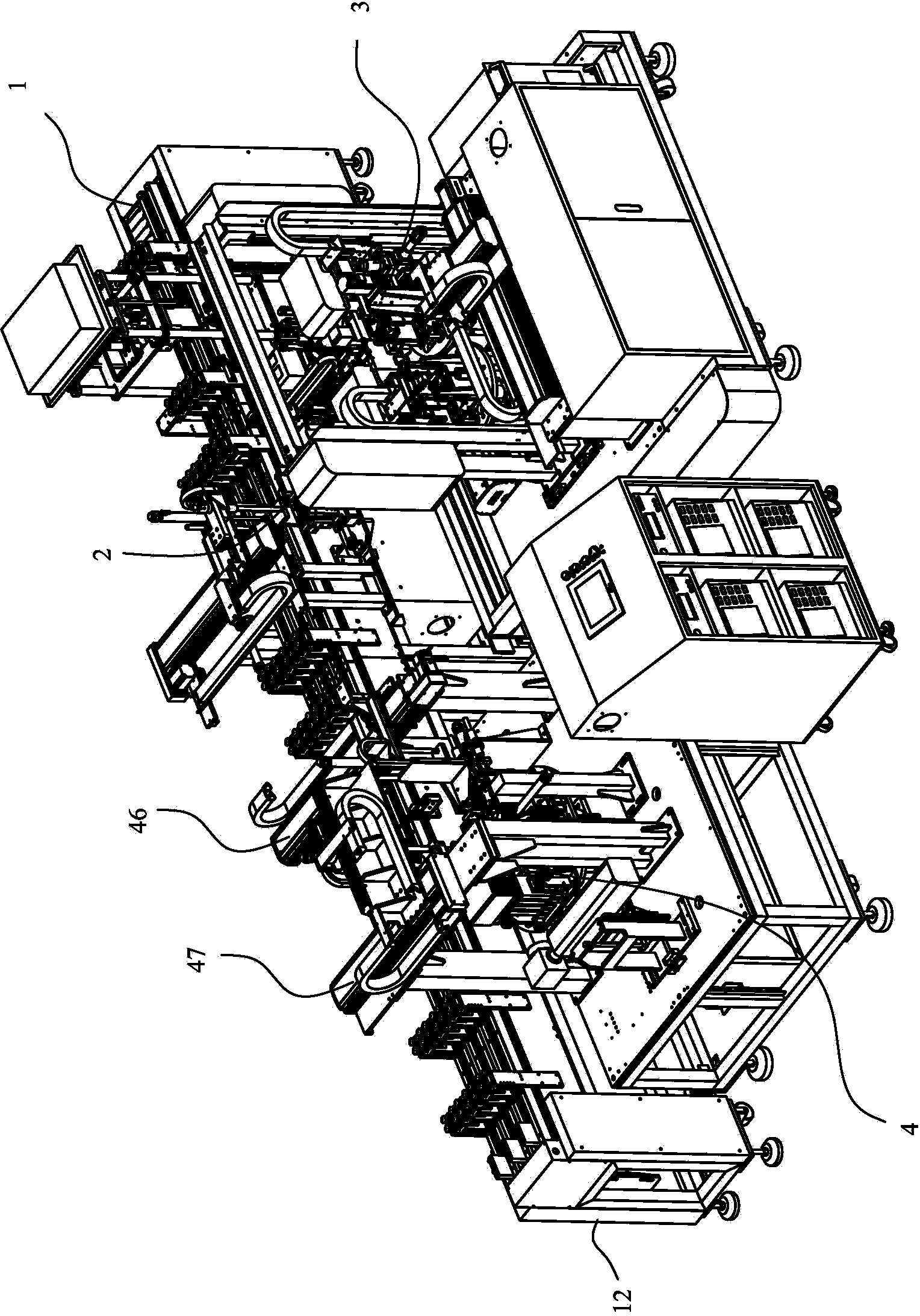
[0041] Please refer to Figure 1 to Figure 13 As shown, it shows the specific structure of the preferred embodiment of the present invention,
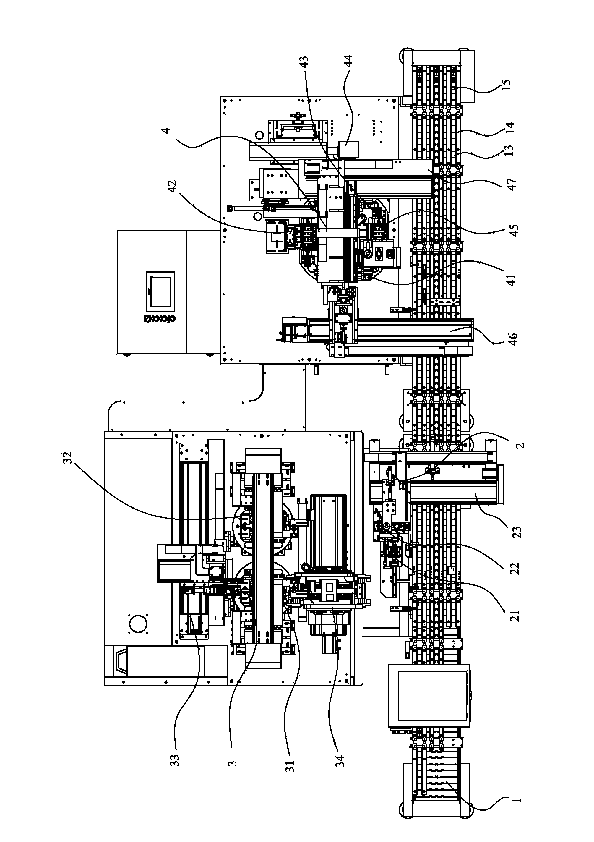
[0042] An automatic equipment for welding and testing of lithium batteries, such as figure 1 As shown, a linear conveying system 1 is included. On the same side of the conveying system 1, a welding system 3 and a detection system 4 are arranged in order according to the conveying direction. A temporary storage system is arranged between the conveying system 1 and the welding system 3. Material system 2.
[0043] Combine image 3 As shown, the temporary storage system 2 includes a temporary storage loading station 21, a temporary storage unloading station 22, and a temporary storage loading and unloading manipulator 23 that fetches and discharges materials back and forth between the two stations and the conveying system 1.
[0044] The welding system 3 is used for welding the end cap 51 of the battery 50 and the outer shell 52, and the combination Figure 5 As shown, the welding system 3 includes a first welding rotating device 31 and a second welding rotating device 32 arranged according to the conveying direction of the conveying system 1. The first welding rotating device 31 and the second welding rotating device 32 have the same structure. A welding loading and unloading manipulator 34 is provided between the first welding rotating device 31, the second welding rotating device 32 and the temporary storage system 1. The welding loading and unloading manipulator 34 is taken out from the temporary storage and loading station 21 of the temporary storage system 2 for waiting. The welding product is put into the welding jig 316 of the first welding rotating device 31 or the second welding rotating device 32, and then the welding loading and unloading manipulator 34 takes out the welding from the welding jig 316 of the first welding rotating device 31 or the second welding rotating device 32 Good products are put into the temporary storage and unloading station 22 of the temporary storage system 2, and the temporary storage and unloading manipulator 23 will take out the welded products in the temporary storage and unloading station 22 and put them on the conveyor belt 13 of the conveyor system 1. Send this product to the inspection system to be tested; outside the first welding rotating device 31, the second welding rotating device 32 is provided with a welding head manipulator 33, and a welding head 35 is installed on the welding head manipulator 33, the welding head 35 Moving back and forth between the first welding rotating device 31 and the second welding rotating device 32, the first welding rotating device 31 and the second welding rotating device 32 rotate in turn to turn the four faces of the battery 50 to be welded to the welding joint 35, the welding head 35 sequentially weld the four surface connection parts of the end cap 51 of the battery 50 and the outer shell 52.
[0045] Combine Image 6 As shown, the first welding rotation device 40 includes a servo motor 320, a welding cam divider 319, and a welding turntable 318. The servo motor 320 drives the welding turntable 318 to rotate through the welding cam divider 319. The welding turntable 318 is provided with a welding fixture 316. A compression block 315 is provided above the welding jig 316.
[0046] The first welding rotating device 40 also includes a pressing support 313, on which a pressing moving platform 314 is provided, and an air cylinder 310 is connected to the pressing moving platform 314. The aforementioned pressing block 315 is arranged in the pressing moving At the lower part of the table 314, the air cylinder 310 drives the pressing and moving table 314 to move up and down. The pressing block 315 moves up and down with the pressing and moving table 314, and the pressing block 315 compresses and loosens the product in the welding fixture 316.
[0047] A light source 312 and a CCD 311 moving with the pressing and moving table 314 are arranged on the left side of the pressing and moving table 314, and the light source 312 is between the CCD 311 and the aforementioned pressing and moving table 314.
[0048] The detection system 4 is used to perform gas leakage detection and short-circuit detection on the battery after welding. The short-circuit detection includes short-circuit detection between electrodes and the casing, and short-circuit detection between electrodes. Combine Figure 7 As shown, the detection system 4 includes a detection loading manipulator 46 and a detection unloading manipulator 47 arranged according to the conveying direction of the conveying system 1, and a detection rotation device is provided between the detection loading manipulator 46 and the detection unloading manipulator 47 40. A loading station 41, a leak detection station 42, a short-circuit detection station 43 and an unloading station 45 are respectively provided on the detection rotating device 40 in four clockwise directions. The loading station 41 is close to the aforementioned detection and loading manipulator 46, a leakage detection mechanism 421 is provided on the outer side of the leakage detection station 42, and a short-circuit detection mechanism 431 is provided on the outer side of the short-circuit detection station 43.
[0049] Combine Figure 8 As shown, the detection rotation device 40 includes a detection motor 49, a detection cam divider 402, and a detection turntable 403. The detection motor 49 drives the detection turntable 403 to rotate through the detection cam divider 402. A detection jig 48 and a rotating outlet barrel 401 are installed, and the rotating outlet barrel 401 uses the rotation axis of the aforementioned detection turntable 403 as a rotation axis.
[0050] The test fixture 48 is used to clamp and fix the battery to be tested, combining Figure 9-11 As shown, the detection fixture 48 includes a clamping drive element, an intermediate fixed splint 490, a movable splint, a guide rod 492, and a linkage mechanism 487. The clamping drive element may be a cylinder, a hydraulic cylinder or a screw controlled by a motor. The movable splint includes a plurality of left movable splints 491 and a plurality of right movable splints 492 respectively placed on both sides of the middle fixed splint 490. The movable splints slide left and right along the guide rod 492. The aforementioned clamping drive element includes a left clamping Drive element 481 and right clamping drive element 482, the left clamping drive element 481 is connected to the outermost left movable splint 491, the right clamping driving element 482 is connected to the outermost right movable splint 485, the middle fixed splint 490 and The left movable splint 491 is connected by a left W-shaped link mechanism 487, and the middle fixed splint 490 and the right movable splint 485 are connected by a right W-shaped link mechanism 487; when clamping products, the left movable splint 491 and the right movable splint 485 are respectively connected The left clamping drive element 481 and the right clamping drive element 482 are symmetrically pulled apart. After the product is placed between the clamping plates, the movable clamping plate is retracted under the action of the clamping drive element, so that the clamped products are uniformly and equally powerful. Clamping.
[0051] The bottoms of the middle fixed splint 490 and the movable splint are respectively provided with a base 486, and the opposite surfaces of the two adjacent bases are respectively provided with protrusions and grooves adapted to each other, and the protrusions extend into the grooves when clamped.
[0052] The testing fixture 48 also includes a first support plate 488, a second support plate 489, and a third support plate 484. The first support plate 488 and the second support plate 489 are connected to both ends of the guide rod 492. The aforementioned left clamping The driving element 481 is mounted on the aforementioned first supporting plate 488, the aforementioned right clamping drive element 482 is mounted on the aforementioned second supporting plate 489, and the aforementioned third supporting plate 484 is arranged on the side of the intermediate fixed splint 490 and the movable splint. .
[0053] A laser marking machine 44 is arranged next to the short-circuit detection mechanism 431 to perform laser marking on products that have passed the short-circuit detection OK, and the marked products are transferred from the short-circuit detection station 43 to the blanking station 45.
[0054] Combine image 3 As shown, the conveying system 1 includes a conveying frame 12, a conveying belt 13, and a conveying guide groove 14. The conveying guide groove 14 is arranged above the conveying belt 13, and the inner walls of both sides of the conveying guide groove 14 are provided with rollers 15. This kind of conveying structure It makes the product move smoothly during the conveying process, has low friction resistance, and maintains good product appearance.
[0055] The above are only the preferred embodiments of the present invention and do not limit the technical scope of the present invention. Therefore, any minor modifications, equivalent changes and modifications made to the above embodiments based on the technical essence of the present invention are still valid. It belongs to the scope of the technical solution of the present invention.

PUM

no PUM

Description & Claims & Application Information

We can also present the details of the Description, Claims and Application information to help users get a comprehensive understanding of the technical details of the patent, such as background art, summary of invention, brief description of drawings, description of embodiments, and other original content. On the other hand, users can also determine the specific scope of protection of the technology through the list of claims; as well as understand the changes in the life cycle of the technology with the presentation of the patent timeline. Login to view more.

Similar technology patents

Vacuum cleaner

InactiveCN103356140Aprevent liftingImprove work efficiency
Owner:SUZHOU HAAN TECH +1

Method of on-line thread feeding and furnace protecting of ironmaking blast furnace and thread feeding device thereof

InactiveCN101109024AShorten the running distanceReduce wire feed resistance
Owner:INST OF METALLURGICAL TECH DONGBEI UNIV SHENYANG

Classification and recommendation of technical efficacy words

  • Shorten the running distance
  • Improve work efficiency

Method of on-line thread feeding and furnace protecting of ironmaking blast furnace and thread feeding device thereof

InactiveCN101109024AShorten the running distanceReduce wire feed resistance
Owner:INST OF METALLURGICAL TECH DONGBEI UNIV SHENYANG

Cooperation service platform facing different source data

InactiveCN101174957AImprove management level and qualityImprove work efficiency
Owner:NANJING UNIV OF FINANCE & ECONOMICS

Screw drilling tool, vertical drilling tool testing method and well inclination simulation testing equipment

InactiveCN111594144AReduced height requirementsImprove work efficiency
Owner:DEZHOU UNITED GASOLINEEUM MACHINERY

Method for intelligent automatic identification of transmission circuit parts

Owner:INFORMATION COMM COMPANY STATE GRID SHANDONG ELECTRIC POWER +2

Keyboard spill-proofing mechanism

ActiveUS7030330B2minimize manufacturing costimprove work efficiency
Owner:LITE ON SINGAPORE PTE LTD
Why Eureka
Try Eureka