Method and system for voltage balancing of energy storage equipment

An energy storage device and voltage balancing technology, applied in current collectors, electric vehicles, electrical components, etc., can solve the problems of inductance, switching tube power devices, difficult selection of switching devices, limited capacitor capacity, etc., to improve the response speed and Reliability, improve energy transfer efficiency, meet the effect of high-power charge and discharge

Active Publication Date: 2016-08-24
GMCC ELECTRONICS TECH WUXI CO LTD
View PDF3 Cites 0 Cited by
  • Summary
  • Abstract
  • Description
  • Claims
  • Application Information

AI Technical Summary

Problems solved by technology

The advantages of this method are: the circuit structure is simple and the cost is low; but the disadvantages are: the charging energy is completely consumed on the voltage regulator tube, the voltage regulator tube will be seriously heated, and the energy waste is serious; the breakdown voltage accuracy of the voltage regulator tube is low, and the dispersion poor performance, which reduces the reliability of the voltage balance circuit, and does not have the ability to balance the whole process in real time. Therefore, the first method is only suitable for occasions where the charging power is very small
Compared with the first two equalization methods, the third DC / DC bidirectional converter method has the advantages of low energy loss, fast voltage equalization speed, and voltage equalization for both charging and discharging states; but the disadvantage is: the required inductance There are many power devices such as switching tubes and switching tubes, the control is complicated and the cost is high
The advantages of this method are: low energy loss, fast voltage equalization speed, and voltage equalization can be performed on both charge and discharge states; but the disadvantage is that the capacity of the capacitor is limited compared with the energy storage unit, and the balance requires multiple switching of the switching network and the balance time Long, the system reliability and balance efficiency are difficult to meet the requirements, and it is difficult to select the switching device in the implementation. If the relay is used, the reliability of the relay itself is poor, and there will be sparks when the contact switch is switched. If the electronic switch is used, there will be defects in the electronic switch itself. The voltage drop causes the balance effect to deteriorate, that is, the voltage difference between the supercapacitor and the flying supercapacitor is too small, and the balance current will be very small

Method used


Image

  • Method and system for voltage balancing of energy storage equipment
  • Method and system for voltage balancing of energy storage equipment
  • Method and system for voltage balancing of energy storage equipment

Examples


Embodiment Construction

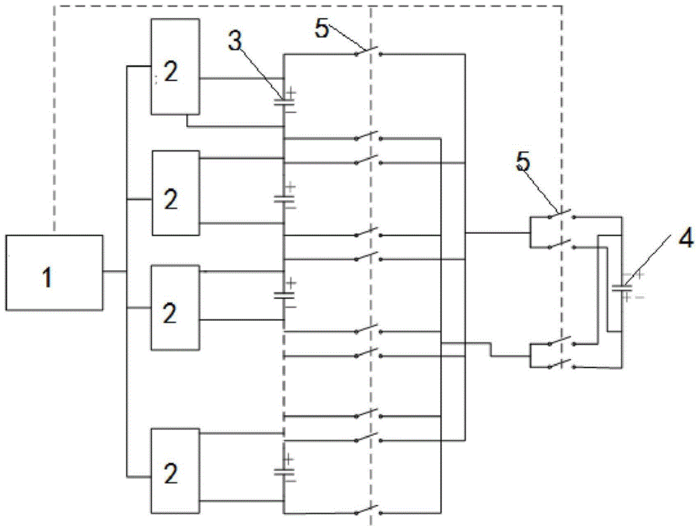
[0036] Such as figure 1 A voltage balance system for energy storage equipment is shown, including a microcomputer controller 1, N single power supplies 2 connected in series, N detection circuits 3, a switch 5 is provided at both ends of each single power supply 2, each single The power supply 2 is connected in parallel with the extreme switch 5, and a balance circuit composed of flying supercapacitors 4.

[0037] The N detection circuits 3 are used to respectively detect the voltage of the N single power sources 2 , the voltage of the flying supercapacitor 4 and the balance current, and transmit them to the microcomputer controller 1 .

[0038] The balance circuit is composed of a single flyover supercapacitor 4, and two switches 5 are respectively arranged at both ends of the flyover supercapacitor 4, which are respectively connected to the same extreme switch terminals of the single power supply.

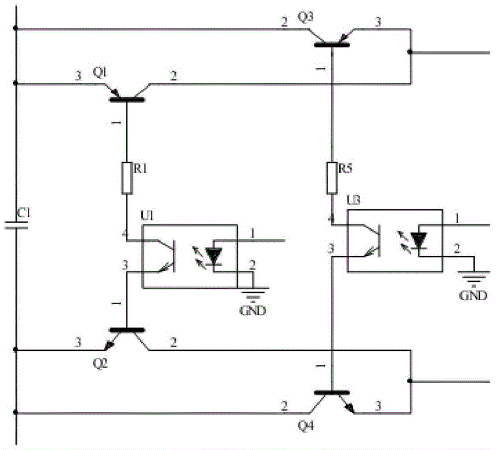
[0039] Such as figure 2 As shown, the switch network switch adopts a trio...


PUM


Abstract

The invention discloses an energy storage equipment voltage balance method. When the voltage difference of single power sources in a series connection (power sources) energy storage equipment reaches a set value, high-voltage single power sources and a flying supercapacitor are in parallel connection to charge the flying supercapacitor, after the flying supercapacitor is charged to a positive voltage or the voltage of one high-voltage single power source is changed to be the lowest, the flying supercapacitor is switched to the next highest-voltage power source and is in parallel connection with the highest-voltage power source, and so repeatedly, voltage balance of energy storage equipment is achieved. The invention further discloses a voltage balance system using the method. According to the energy storage equipment voltage balance method and system, the single supercapacitor is used as a flying element to be in parallel connection with the single power sources in the opposite direction, the problem that traditional voltage differences are too small is solved, the demand for large-power charging and discharging is met, sufficient capacity can further be provided, and energy transfer efficiency is improved. Circuits are simple, and each single power source is used as a working power source for controlling a switching transistor. The single power sources are used for being in parallel connection with the supercapacitor in a reversed polarity mode, and the response speed and the reliability of the system are improved.

Description

technical field [0001] The invention relates to the technical field of power management systems of energy storage devices, in particular to a method and system for voltage balance in the management system of energy storage devices. Background technique [0002] With the rapid development of new energy industries such as new energy vehicles and new energy power generation, new energy storage has become a key technology. Products used for new energy storage mainly include lead-acid batteries, lithium-ion batteries, and supercapacitors. The voltage of these products is very low, generally less than 5V. However, these new energy storage applications often have a voltage of hundreds or even thousands of V. Therefore, in practical applications, it is necessary to combine the monomers of energy storage products in series and parallel, and design the series and parallel structure according to the required voltage and capacity. For example, a 600V400AH bus power system requires bat...

Claims


Application Information

Patent Timeline
Patent Type & Authority Patents(China)
IPC IPC(8): H02J7/00
Inventor 孙伟王俊华胡期峰
Owner GMCC ELECTRONICS TECH WUXI CO LTD
Why Eureka
Try Eureka