Phase-shift full-bridge converter circuit and control method

A technology of converting circuits and phase-shifting full bridges, applied in control/regulation systems, DC power input conversion to DC power output, electrical components, etc. Reduce the efficiency of the whole machine and other issues to achieve the effect of reducing the EMI of the whole machine, reducing switching losses, and improving the efficiency of the whole machine

Active Publication Date: 2014-07-02
成都芯通软件有限公司
View PDF5 Cites 12 Cited by
  • Summary
  • Abstract
  • Description
  • Claims
  • Application Information

AI Technical Summary

Problems solved by technology

[0003] 1) At light load, the energy stored in the resonant inductor L1 is not enough to drain the drain-source capacitance charge of the rear axle MOS tubes (Q3, Q4), which makes the rear axle work in a hard switching state at this time, resulting in increased switching loss and severe heat generation
[0004] 2) The reverse recovery of the rectifier diode on the secondary side of the transformer is serious, which leads to low efficiency of the whole machine. When the traditional phase-shifted full bridge works, the rear bridge works in the ZVS state, causing the secondary rectifier diode to be hard-off, so the diode has reverse recovery loss. and increases with output power
[0005] 3) During the period when the primary current of the traditional phase-shifting full-bridge transformer is from positive undershoot to negative or from negative upshoot to positive, the current of the output filter inductor L2 cannot change suddenly, so the primary side of the transformer is "short-circuited" due to the freewheeling

Method used


Image

  • Phase-shift full-bridge converter circuit and control method
  • Phase-shift full-bridge converter circuit and control method
  • Phase-shift full-bridge converter circuit and control method

Examples


Example Embodiment

[0033] The present invention will be further described in detail below in conjunction with specific embodiments. However, it should not be understood that the scope of the above-mentioned subject of the present invention is limited to the following embodiments, and all technologies implemented based on the content of the present invention belong to the scope of the present invention.
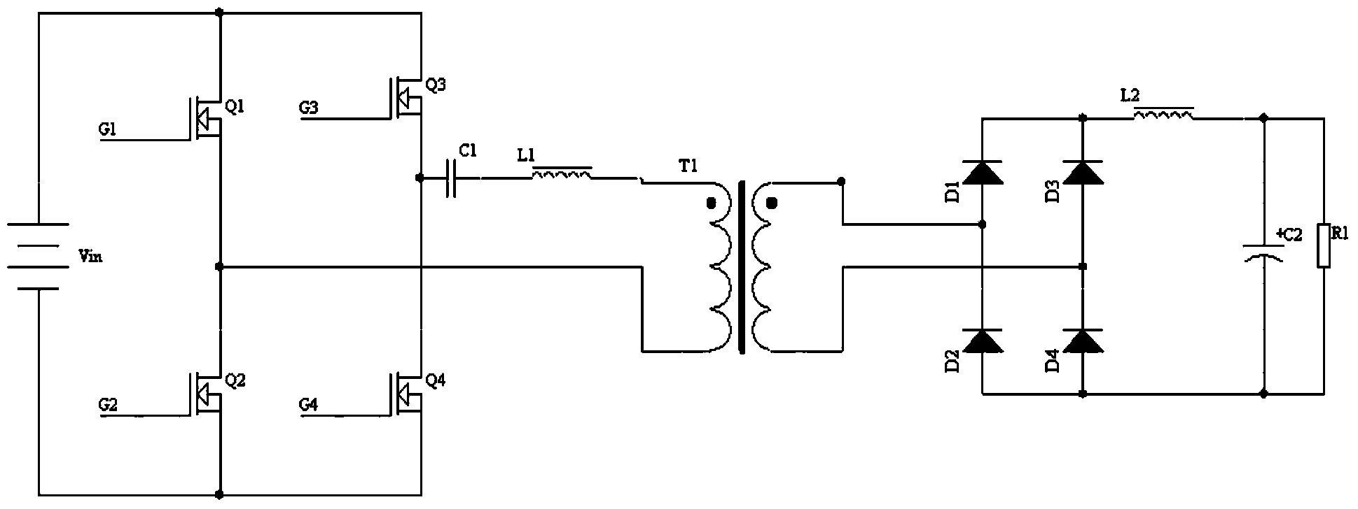
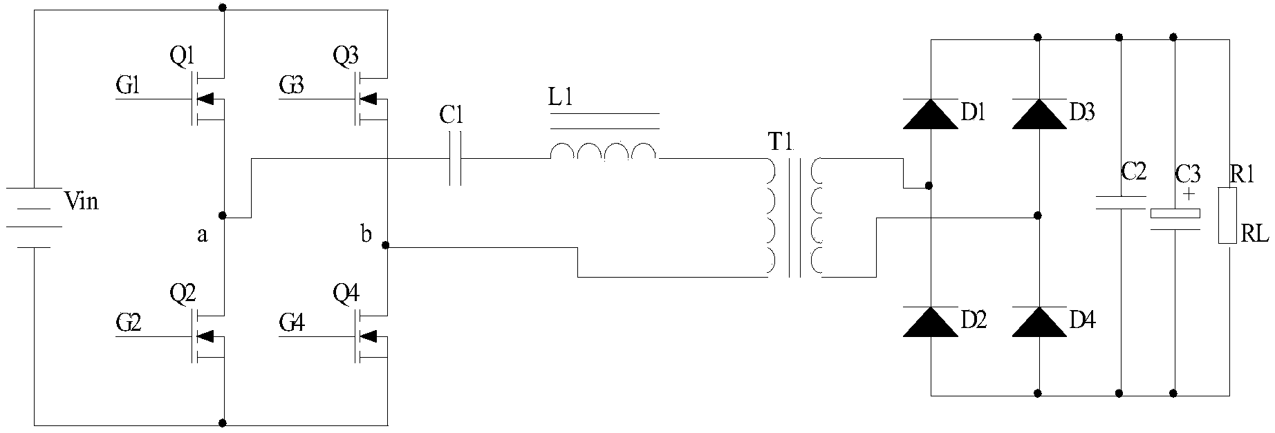
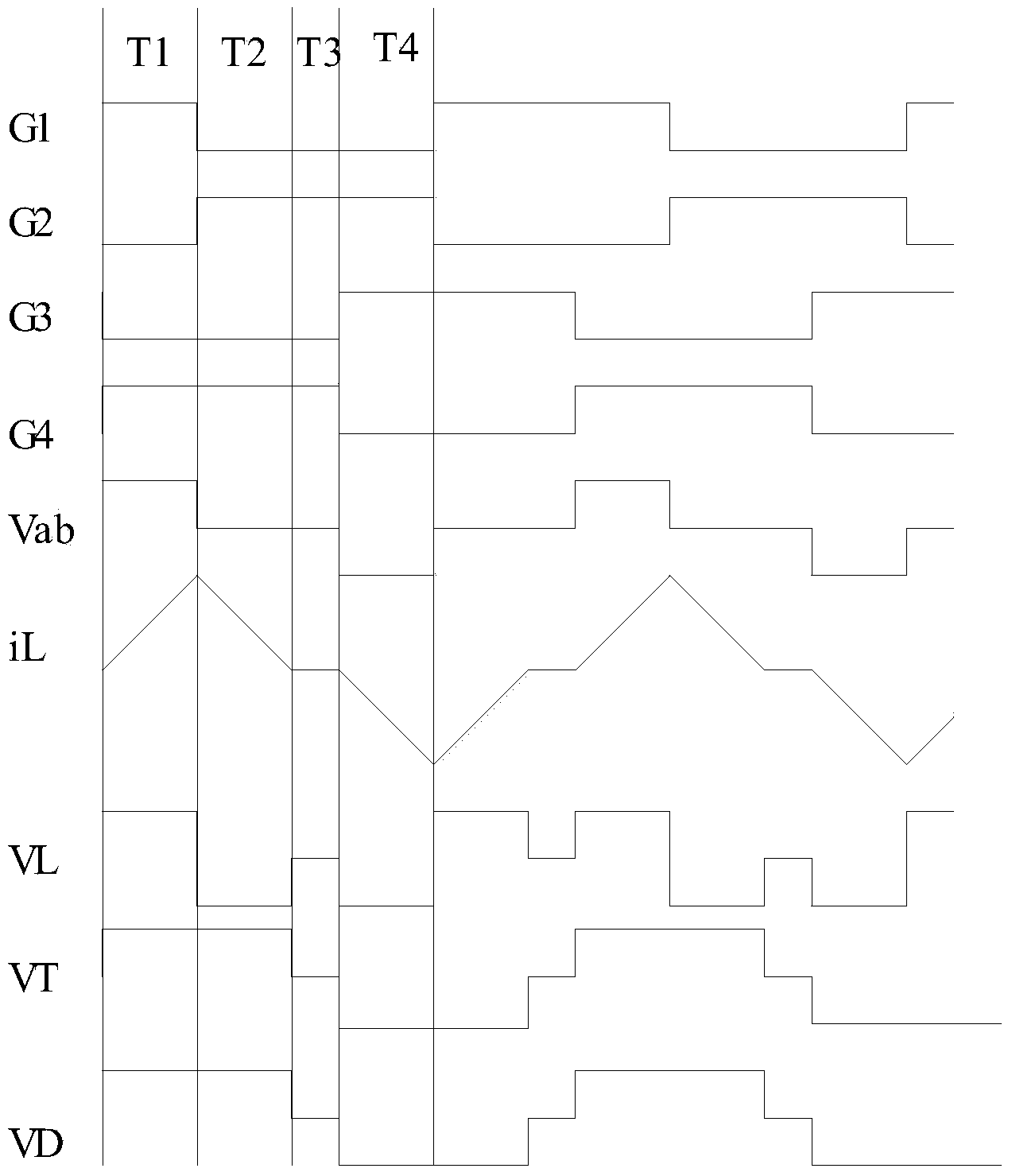
[0034] The control method of the phase-shifted full-bridge conversion circuit of the present invention, see figure 2 with image 3 , Divide a working cycle of the phase-shifted full-bridge conversion circuit into the following stages: Among them, G1, G2, G3, G4 are the applied gate voltages from MOS tube one to MOS tube four (Q1-Q4), and iL is the transformer primary The current of the resonant inductor L1 on the side, VL is the voltage of the resonant inductor L1, VT is the voltage on the primary side of the transformer T1, Vin is the input DC voltage, Vo is the output DC voltage, and VD is figu...


PUM


Abstract

The invention discloses a phase-shift full-bridge converter circuit which comprises a transformer, a lead bridge arm, a lag bridge arm and an output circuit. The lead bridge arm is formed by serially connecting a first MOS tube and a second MOS tube, the connection point of the two MOS tubes is sequentially connected with one end of a primary side of the transformer through a capacitor and a resonant inductor, and the capacitor and the resonant inductor are connected in series. The lag bridge arm is formed by serially connecting a third MOS tube and a fourth MOS tube, the connection point of the two MOS tubes is connected with the other end of the primary side of the transformer, and input direct-current voltage is applied to the positions between the connection point of the first MOS tube and the second MOS tube and the connection point of the third MOS tube and the fourth MOS tube. The output circuit is composed of four rectifier diodes and an output capacitor. The voltage of the two ends of the output capacitor is output direct-current voltage. The invention further discloses a control method of the phase-shift full-bridge converter circuit. By means of the circuit and the method, full-bridge soft switching of the phase-shift full-bridge converter circuit is achieved, switching loss is reduced, and efficiency is improved.

Description

technical field [0001] The invention relates to the technical field of phase-shifting full-bridge conversion, in particular to a medium and high-power phase-shifting full-bridge conversion circuit and a control method. Background technique [0002] The phase-shifted full-bridge conversion topology is one of the most widely used topologies in high-power DC / DC converters, and it is also a circuit structure that has been studied more. It uses the charge-discharge resonance mode between the inductor and the capacitor to enable the full-bridge MOS tube to realize soft switching when it is turned on to reduce switching loss, thereby improving the switching frequency and overall efficiency without increasing switching loss. However, there are many defects in the traditional phase-shifted full-bridge circuit. figure 1 The circuit shown, the main problems are: [0003] 1) At light load, the energy stored in the resonant inductor L1 is not enough to drain the drain-source capacitanc...

Claims


Application Information

Patent Timeline
IPC IPC(8): H02M3/335
Inventor 曾帮远
Owner 成都芯通软件有限公司
Why Eureka
Try Eureka