Pipe type membrane assembly coated with cascaded structure on inner wall

A series structure, tubular membrane technology, applied in the field of membrane separation, can solve the problems of difficulty in realizing small batch on-line pervaporation dehydration, poor sealing performance of the outer wall coating membrane tube, and low dehydration efficiency of a single membrane module. Simple, good sealing, not easy to leak

Active Publication Date: 2014-07-09
宁波信远膜工业股份有限公司 +1
View PDF4 Cites 11 Cited by
  • Summary
  • Abstract
  • Description
  • Claims
  • Application Information

AI Technical Summary

Problems solved by technology

Inorganic membranes mostly use tubular membrane modules, which can be coated on the inner wall or outer wall. The existing tubular membrane modules in China all use outer wall coated membrane tubes. The sealing structure is complex and the sealing performance is poor. No, the outer wall tube is prone to leakage under the dual action of fluid pressure and vacuum pressure
In addition, when tubular membranes are used in pervaporation and steam permeation processes, the filling area of ​​the membrane modules is required to be large enough, and the membrane modules composed of outer wall tubes can only be in parallel structure. When a single fluid passes through the membrane modules, The contact area between the organic solvent feed liquid and the membrane module is small, which leads to low dehydration efficiency of a single membrane module, and the sealing of the outer wall coated membrane tube is not good, the tubes cannot be connected in series, and it is difficult to realize small batch on-line permeation vaporization dehydration

Method used


Image

  • Pipe type membrane assembly coated with cascaded structure on inner wall
  • Pipe type membrane assembly coated with cascaded structure on inner wall
  • Pipe type membrane assembly coated with cascaded structure on inner wall

Examples


Embodiment 1

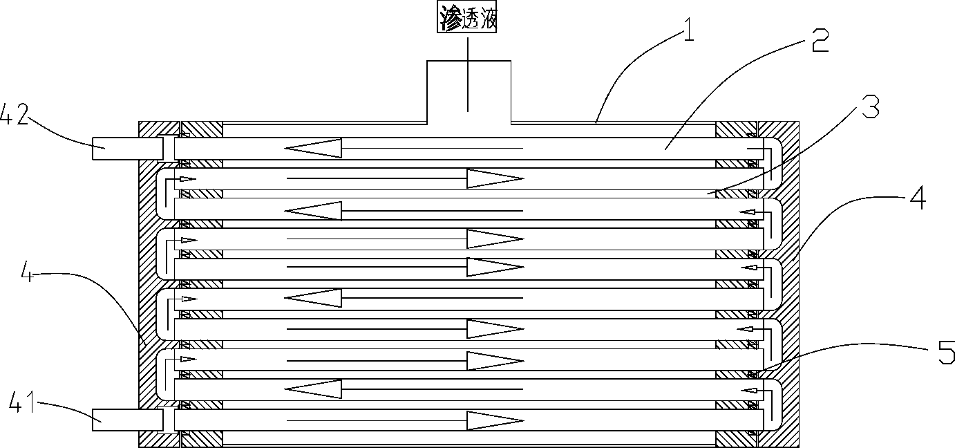
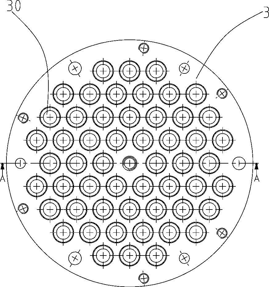
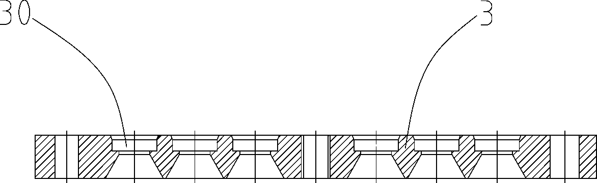
[0025] see Figure 1 to Figure 6 As shown, the inner wall of the present invention is coated with a series structure tubular membrane module mainly a shell 1, a group of tubular membranes 2, two pairs of flanges 3, 4 and seals 5, and the shell 1 covers all the tubular membranes. film2.

[0026] The inner wall of the tubular membrane 2 is coated with a separation layer. Compared with the sealing structure of the outer wall tube, the sealing structure with a separation layer on the inner wall is simpler and has better sealing reliability. It is not easy to leak under the environment, and the sealing structure is more effective in the presence of vacuum pressure.

[0027] Two pairs of flanges are arranged symmetrically at both ends of the tubular membrane 2, and each pair of flanges is composed of a fixed flange 3 and a channel flange 4, and a plane is passed between the fixed flange 3 and the channel flange 4. Contact, under the pressure of the bolts to prevent leakage between...

Embodiment 2

[0035] see Figure 1 to Figure 6 As shown, the separation layer is a pervaporation membrane supported by ceramics, which is a pervaporation membrane coated with an inorganic membrane on a ceramic support body, and the rest of the technical solutions are the same as in Embodiment 1.


PUM


Abstract

The invention discloses a pipe type membrane assembly coated with a cascaded structure on an inner wall, belonging to the technical field of membrane separation. The pipe type membrane assembly comprises a pipe shell, a set of pipe type membranes and two pairs of flanges, wherein the inner walls of the pipe type membranes are coated with separation layers; each pair of the flanges is composed of a fixed flange and a runner flange; each fixed flange is provided with through holes with section shapes, quantities and positions which correspond to those of the pipe type membranes; the runner flanges are provided with runner grooves; openings of the two pipe type membranes are formed in the runner grooves and are matched with the runner grooves so as to form the cascaded structure. Compared with the prior art, the pipe type membrane assembly has the advantages that small-batch online pervaporation dehydration can be realized; the contact area between organic solvent material liquid and the membrane assembly is large and the mobility of separated substances is good; the sealing performance, the temperature resistance and the solvent resistance are good; the dehydration efficiency is high and the time requirements on developing green economy are met.

Description

technical field [0001] The invention belongs to the technical field of membrane separation, and in particular relates to an inner wall coated tubular membrane module with a serial structure. Background technique [0002] With the rapid development of industry, various organic solvents are widely used, including chemical solvents such as alcohols, esters, ketones, ethers, and aromatic compounds, which are used in energy, medicine, biology and other fields, and play an important role in the national economy. effect. [0003] Organic solvent dehydration is an important link in the production and use of organic solvents. Traditional separation methods mainly include general chemical methods, adsorption methods, and rectification methods. Most organic solvents and water form azeotropes or near-boilers, and it is difficult to remove water by ordinary distillation techniques. Traditional azeotropic distillation and extractive distillation technologies need to add a third compone...

Claims


Application Information

Patent Timeline
Patent Type & Authority Applications(China)
IPC IPC(8): B01D63/06B01D61/36
Inventor 袁奕琳凌福康李玉芳施晨
Owner 宁波信远膜工业股份有限公司
Why Eureka
Try Eureka