Photomultiplier of electrostatic focusing micro-channel plates

A photomultiplier tube and microchannel plate technology, applied in the direction of electron multiplier tubes, electron multiplier details, electron multiplier anode devices, etc., can solve the problems of slow progress, unpredictable resistance, low coverage, etc. The effect of time difference, high gain, and reduction of signal distortion

Active Publication Date: 2014-07-09
INST OF HIGH ENERGY PHYSICS CHINESE ACAD OF SCI +2
View PDF4 Cites 25 Cited by
  • Summary
  • Abstract
  • Description
  • Claims
  • Application Information

AI Technical Summary

Problems solved by technology

With the development of high-energy physics, its requirements for photodetectors continue to increase. First, because the coverage of the photocathode of the above-mentioned large-scale photomultiplier tube is not high, it is difficult to reach 80% if it is formed into an array. The design of the focusing electrode and the dynode, the photoelectrons coming from different directions, after passing through the focusing electrode and the dynode, the transit time distribution of the electrons becomes wider, which is not conducive to the accurate measurement of neutrinos
In recent years, the Argonne National Laboratory of the United States has formed a cooperation group with its domestic microchannel plate (MCP) and photocathode-related units to develop a 200×200mm close-fit focusing microchannel plate photomultiplier tube (MCP-PMT). Cathode technology and ALD technology try to solve the above-mentioned difficulties faced by large-size photomultiplier tubes, but the technology is difficult and progress is slow
Scientists from the Institute of High Energy Physics of the Chinese Academy of Sciences proposed to make a photocathode that completely covers the inner surface of a spherical transparent vacuum container, place an MCP or similar electron multiplier in the center of the sphere, and use electron optics design to make photoelectrons from everywhere It can effectively hit the electron multiplier, and filed a patent application with the State Intellectual Property Office on June 10, 2009, and obtained the patent right on June 27, 2012 (name of invention: a photomultiplier tube, application number: 200910147915.4, authorized announcement number: CN101924007B), this patent proposes to make full use of the characteristics of the transmissive cathode and the reflective cathode for the first time, thereby improving the quantum efficiency of the photocathode, and adopting a reasonable electron optical design to ensure that the electron multiplier can collect nearly 4π Optoelectronics within a solid angle, but as far as it uses MCP as an electron multiplier, especially 2 to 3 blocks are directly connected in series as an electron multiplier. In actual production, it is difficult to clean and degas the electrons. After degassing, each MCP The resistance is unpredictable, and it is difficult to realize that each MCP is in the best working state. The direct series connection of two MCPs generally has a gain of ~10 5 magnitude, even with an amplifier, sometimes it is difficult to detect a single photoelectron

Method used


Image

  • Photomultiplier of electrostatic focusing micro-channel plates
  • Photomultiplier of electrostatic focusing micro-channel plates
  • Photomultiplier of electrostatic focusing micro-channel plates

Examples


Embodiment Construction

[0037]The present invention will be further described below in conjunction with the accompanying drawings and preferred embodiments. It should be noted that the embodiments described here are for illustration only and do not limit the present invention.

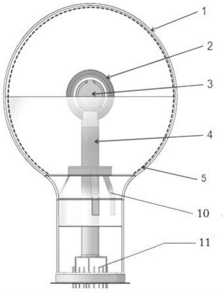
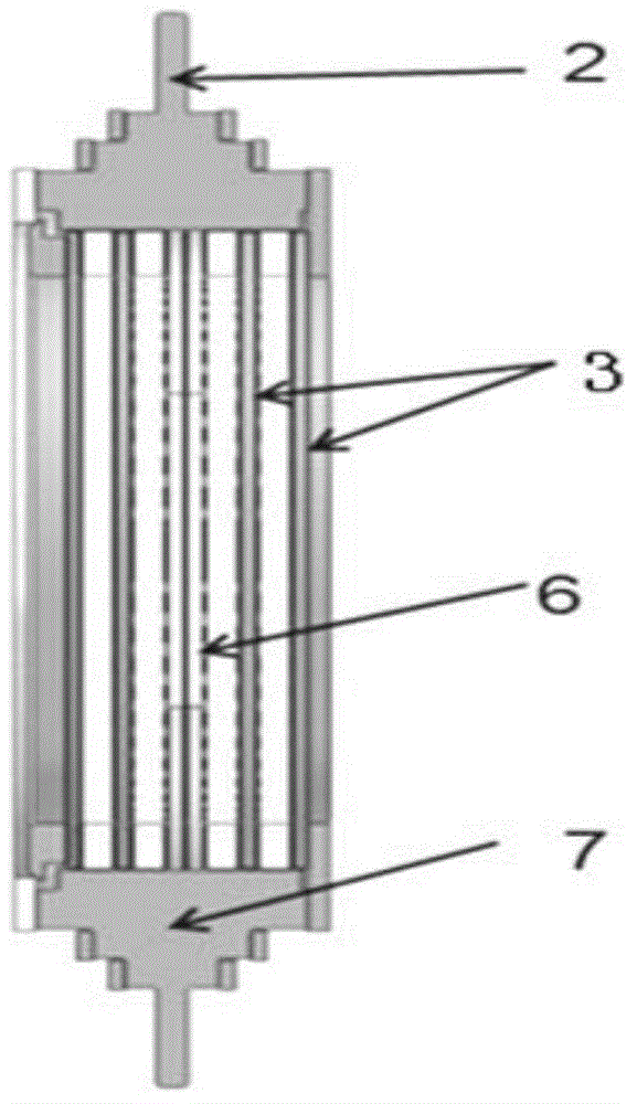
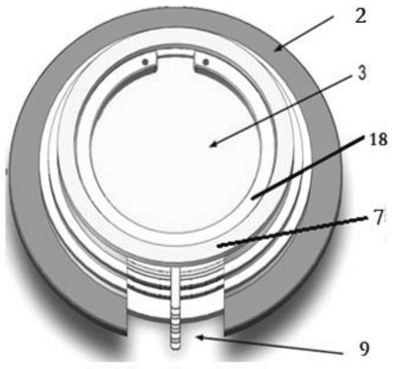
[0038] Such as figure 1 As shown, the photomultiplier tube of the first embodiment of the present invention mainly includes a spherical or ellipsoidal vacuum vessel 1 made of glass, a photocathode 5 attached to the inner surface of the glass, a focusing electrode 2, an electron multiplier 3, and an anode 6 ( See figure 2 ) and support column 4, focusing electrode 2, electron multiplier 3, and anode 6 are integrated through ceramic skeleton 7 (such as figure 2 shown), the centers of the three are coaxial, and are fixed at the center of the vacuum vessel 1 by the support column 4, and the support column 4 is fixed by the three claws 10 and the glass core column 11 below.

[0039] The electron multiplier of the present inve...


PUM


Abstract

The invention discloses a photomultiplier of electrostatic focusing micro-channel plates. The photomultiplier comprises a photocathode, an electron multiplier, an anode, a focusing electrode, a power supply electrode and a supporting post for supporting the focusing electrode, the electron multiplier and the anode, the focusing electrode, the electron multiplier and the anode are arranged in a glass vacuum container, and a signal lead of the anode and the power supply electrode penetrate through the glass vacuum container to be connected with an external circuit. The photomultiplier is characterized in that the centers of the focusing electrode, the electron multiplier and the anode are coaxial, the electron multiplier comprises the two pairs of micro-channel plates arranged in parallel, and certain gaps are reserved between the micro-channel plates. Compared with the prior art, all stages of voltages of the micro-channel plates are independently adjusted, and high gains and good photoelectron spectra are achieved.

Description

technical field [0001] The invention relates to a vacuum photodetection device, specifically a photomultiplier tube, especially a photomultiplier that focuses photoelectrons generated by a large-size photocathode on an electron multiplier composed of a microchannel plate assembly through an electrostatic focusing electrode Tube. technical background [0002] As a photomultiplier tube (PMT) that converts weak optical signals into electrical signals, it is widely used in various fields of the national economy because of its high sensitivity and fast time response. Judging from the development direction of current applications, one is miniaturization, and the other is giantization. The latter will play an irreplaceable role in the detection of neutrinos in high-energy physics. Hamamatsu Photonics Co., Ltd. of Japan and Photonis Company of France have successively developed 8-inch, 10-inch, 12-inch, 13-inch and 20-inch ellipsoidal or near-spherical photomultiplier tubes. The ph...

Claims


Application Information

Patent Timeline
Patent Type & Authority Applications(China)
IPC IPC(8): H01J43/06H01J43/12
CPCH01J43/246
Inventor 刘术林刘虎林司曙光钱森田进寿孙建宁赵天池赛小锋王贻芳王志宏韦永林苏德坦衡月昆曹俊
Owner INST OF HIGH ENERGY PHYSICS CHINESE ACAD OF SCI
Why Eureka
Try Eureka