Method for measuring torsional vibration of shafting

A technology of torsional vibration and measurement methods, which is applied in the direction of measuring devices, measuring ultrasonic/sonic/infrasonic waves, instruments, etc., can solve the problems of increased installation difficulty, inaccurate measurement results, and easy-wear sensors, etc., to achieve strong engineering applicability, The effect of simple measurement process and accurate measurement results

Active Publication Date: 2014-07-16
HARBIN ENG UNIV
View PDF6 Cites 6 Cited by
  • Summary
  • Abstract
  • Description
  • Claims
  • Application Information

AI Technical Summary

Problems solved by technology

Due to the small number of teeth and the radial installation of the sensor, the sudden change in displacement is not obvious. At a low speed of 100rpm, serious signal distortion has already occurred, and the measurement error is relatively large. Moreover, this kind of gear needs special processing, which is not suitable for practical engineering applications. widely
In the second document, two sets of eddy current sensors are radially installed at the symmetrical position of the gear plate at a distance of 180°. The purpose is to reduce the interference of lateral vibration, but it cannot completely eliminate it.
In the actual measurement, most of the gears are covered by the casing, and if two measuring points are arranged symmetrically, the installation will be more difficult and difficult to achieve
The latter two documents both use the CTS-A12M-2ANA eddy current sensor from CORON, Taiwan. Its advantage is that it can integrate signal acquisition and shaping, and the output signal is a square wave. Count to get the average speed, not the instantaneous speed, the measurement result is not accurate
Since the probe is very close to the top surface of the tooth when the sensor is installed radially, the tooth surface must be processed with high precision,

Method used


Image

  • Method for measuring torsional vibration of shafting
  • Method for measuring torsional vibration of shafting
  • Method for measuring torsional vibration of shafting

Examples


Embodiment Construction

[0012] The present invention is described in more detail below in conjunction with accompanying drawing example:

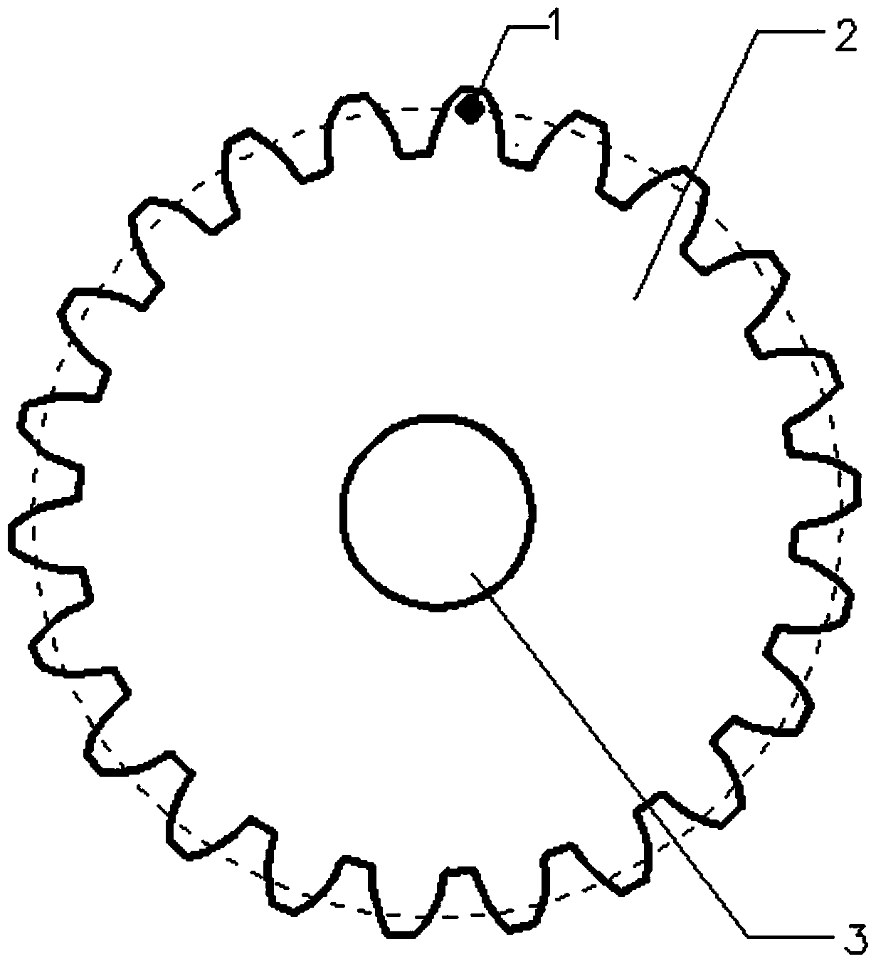
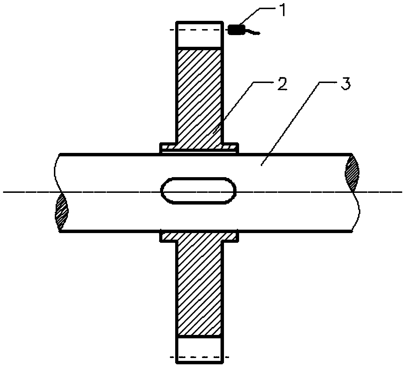
[0013] combine Figure 1~2 , a method for measuring torsional vibration of a shaft system in the present invention, the gear to be tested is installed on the shaft of the gear to be tested, the eddy current sensor is axially installed on the side of the gear to be tested, the eddy current sensor is parallel to the axis of the gear to be tested, and the eddy current sensor Align the probe with the position of the index circle. After the gear shaft and the gear under test rotate, each time a tooth of the gear under test passes through the eddy current sensor, the eddy current sensor measures a pulse signal and records the pulse width at the same time. The width obtains the instantaneous angular velocity of the measured gear shaft, draws the instantaneous angular velocity into an instantaneous angular velocity curve, integrates the instantaneous angular velocity curv...


PUM


Abstract

The invention provides a method for measuring the torsional vibration of shafting. A measured gear is mounted on a measured gear shaft, an electrical vortex sensor is axially mounted on the side face of the measured gear, the electrical vortex sensor is parallel to the axis of the measured gear, and a probe of the electrical vortex sensor aligns to the position of a reference circle. After the measured gear shaft and the measured gear rotate, each tooth of the measured gear passes through the electrical vortex sensor, the electrical vortex sensor measures one pulse signal, and meanwhile a pulse width is recorded. The instantaneous angular velocity of the measured gear is acquired through the pulse width, the instantaneous angular velocity is drawn to be an instantaneous angular velocity curve, the instantaneous angular velocity curve is integrated, and therefore the angular domain curve of the torsional vibration of the measured gear is obtained. According to the method for measuring torsional vibration of shafting, the sensor is mounted in the axial direction, so that measuring errors caused by gear tooth face machining errors are avoided, the roughness of the top surface of each tooth is not required, the engineering applicability is high, and a measuring result is more precise.

Description

technical field [0001] The invention relates to a vibration measurement method, in particular to a shaft vibration measurement method. Background technique [0002] In vibration engineering, when designing and constructing new ships, it is necessary to calculate and analyze the torsional vibration of the shafting system and inspect the real ship to ensure that the torsional vibration of the shafting system is always in a safe state or draw out the restricted speed zone. The test conditions on the actual ship are limited, and accurate, effective and convenient test methods are extremely important for torsional vibration measurement. [0003] The traditional torsional vibration measurement of the gear shaft system generally adopts the method of radially installing the eddy current sensor or the magnetoelectric sensor on the gear, and aligning the front face with the tooth top surface of the gear tooth. After literature search, it was found that 4 documents involved the use of...

Claims


Application Information

Patent Timeline
IPC IPC(8): G01H11/00G01H11/06
Inventor 李玩幽韩霄赵博之钟佰志张相元于姝雯
Owner HARBIN ENG UNIV
Why Eureka
Try Eureka