
Frequency divider and wireless communication device

A frequency divider and signal technology, applied in the field of communication, can solve the problems of large consumption of resources, unfavorable for low power consumption, low noise, inconvenient configuration, etc., and achieve the effect of simple structure, strong configurability, and easy expansion.

Active Publication Date: 2014-07-16
HUAWEI TECH CO LTD
View PDF5 Cites 21 Cited by
  • Summary
  • Abstract
  • Description
  • Claims
  • Application Information

AI Technical Summary

Problems solved by technology

In this solution, multiple frequency dividers are completely independent, which consumes a lot of resources, which is not conducive to the realization of low power consumption and low noise
And the multi-channel frequency divider is strictly started according to the required timing, so the corresponding startup circuit is required, and the timing of the startup circuit is closely related to the frequency division ratio, which is not easy to realize configurable

Method used


Image

  • Frequency divider and wireless communication device
  • Frequency divider and wireless communication device
  • Frequency divider and wireless communication device

Examples


Embodiment Construction

[0044] The embodiments of the present invention will be described in detail below with reference to the accompanying drawings. It should be clear that the described embodiments are only a part of the embodiments of the present invention, rather than all the embodiments. Based on the embodiments of the present invention, all other embodiments obtained by those of ordinary skill in the art without creative work shall fall within the protection scope of the present invention.

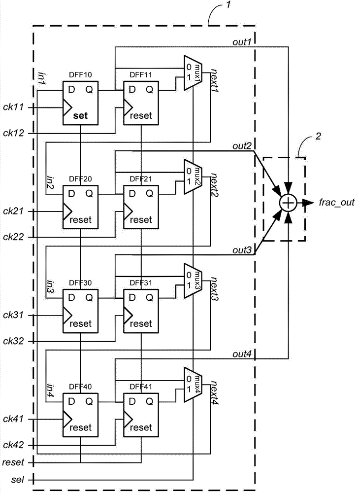
[0045] figure 2 A frequency divider provided by an embodiment of the present invention includes: a shift register unit 1 and an output frequency synthesis unit 2.

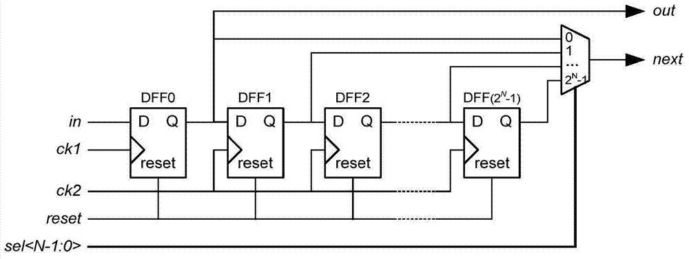
[0046] The shift register unit 1 is a cyclic cascade structure composed of multiple basic units in series; the circuit structure of the basic unit can be specifically referred to image 3 As shown, each level of basic unit includes 2 N A series of D flip-flops (DFF) and a multiplexer (mux), the 2 N D flip-flops connected in series use DFF1,..., DFF...


PUM


Abstract

The embodiment of the invention discloses a frequency divider and a wireless communication device. The frequency divider comprises a shifting register unit and an output frequency synthesis unit, wherein the shifting register unit comprises multiple basic units cascaded circularly; each basic unit comprises 2N D flip-flops connected in series and a multi-path gating device, output of the 2N D flip-flops connected in series is connected into the multi-path gating device, and the output of the multi-path gating device is connected with input of the basic unit at a next level; the phase of clock signals connected into other 2N-1 D flip-flops except the first D flip-flop at the signal input end of the basic unit at each level is lagged than that of clock signals connected into the first D flip-flop by a M / 2 clock period; the phase of clock signals connected to the first D flip-flop in the basic unit at the next level is lagged than that of clock signals connected into other 2N-1 D flip-flops in the basis unit at the previous level by three fourths clock period; output signals of the first D flip-flops in the basic units at all the levels are superposed through the output frequency synthesis unit to generate fractional frequency output signals.

Description

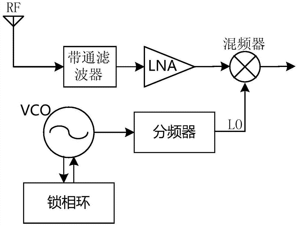
Technical field [0001] The present invention relates to the field of communication technology, in particular to a frequency divider and wireless communication equipment. Background technique [0002] In the transceiver (Transceiver, TRX) circuit of the radio frequency communication system, such as figure 1 As shown, the received RF signal passes through a band-pass filter to filter out-of-band interference, and is amplified by a low noise amplifier (LNA) to reduce the impact of the subsequent circuit noise, and then sent to the mixer input. Mixing with the local oscillator (LO) signal. Therefore, a stable LO signal is required as a reference signal for the transceiver link. This signal is obtained by dividing the output frequency of a Voltage-Controlled Oscillator (VCO). In order to generate an accurate and stable frequency at the output of the VCO, a phase-locked loop is usually used to drive the VCO in the feedback loop to make the oscillator Frequency (or phase) accurately t...

Claims


Application Information

Patent Timeline
IPC IPC(8): H03K23/42H03K23/54H03L7/197
CPCG06F1/022H03K21/10H03K23/667H03L7/16H04L7/033
Inventor 马昭鑫朱年勇
Owner HUAWEI TECH CO LTD
Learn More