Eureka AIR delivers breakthrough ideas for toughest innovation challenges, trusted by R&D personnel around the world.

Variable timing system of engine valve

A technology of engine valves and timing systems, which is applied in the direction of engine components, machines/engines, mechanical equipment, etc., can solve the problems of complex engine structure and high cost of use, and achieve simple structure, cost saving and good operation stability Effect

Inactive Publication Date: 2014-07-30
CHONGQING JIAOTONG UNIVERSITY
View PDF5 Cites 4 Cited by
  • Summary
  • Abstract
  • Description
  • Claims
  • Application Information

AI Technical Summary

Problems solved by technology

[0002] The engine valves are opened and closed by crankshaft power and chain sprocket transmission. During the intake stroke, the piston sucks air into the cylinder for fuel injection and combustion. The expanding gas pushes the piston to move and do work to generate power, and then discharges the combustion exhaust gas to measure the engine power. The size parameter is "displacement", engine displacement = cylinder working volume × number of cylinders, in theory, the larger the cylinder volume, the more air intake, the greater the output power, but the actual situation is that the intake process will be affected The direct impact of the opening and closing conditions of the valve, the variable valve control device in the prior art, when the engine is running at low speed, reduces the opening of the valve by controlling the position distance between the crankshaft and the camshaft to provide less gas , when the engine runs at high speed, the control device restores the valve opening to provide more gas, and realizes the economical operation of the internal combustion engine in this way. The valve control device complicates the internal structure of the engine and increases the cost of use

Method used


Image

  • Variable timing system of engine valve
  • Variable timing system of engine valve

Examples


Embodiment Construction

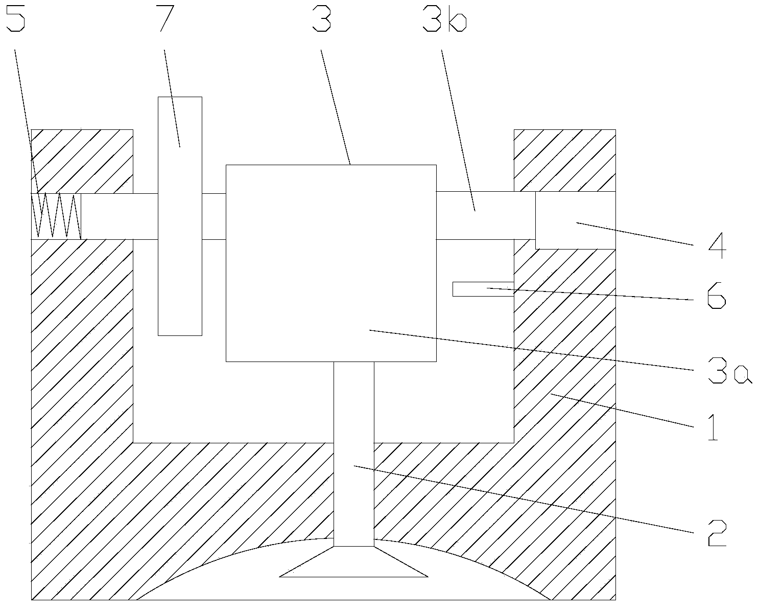
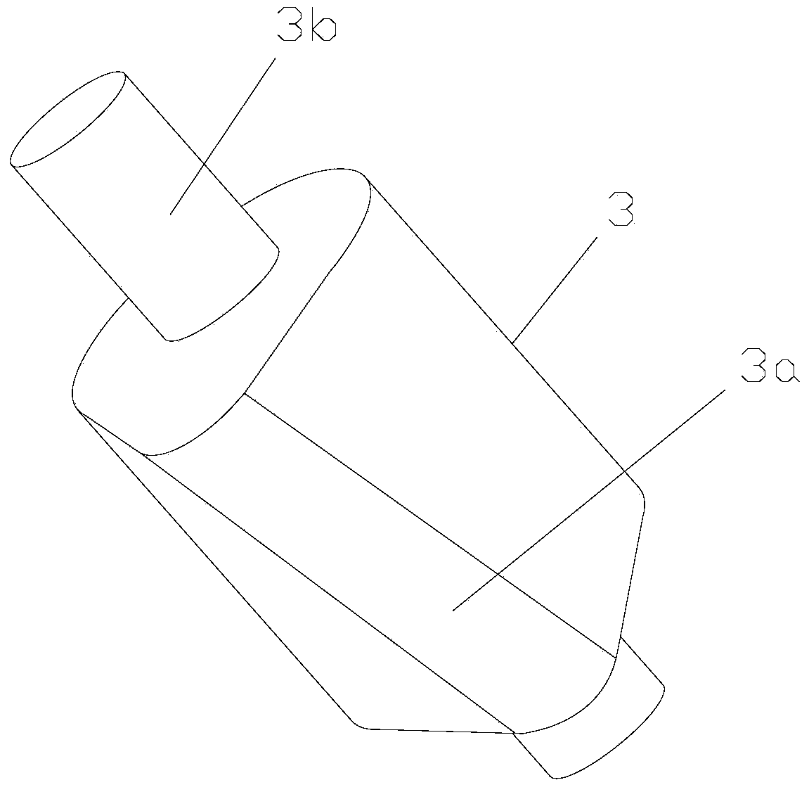
[0012] figure 1 It is a structural schematic diagram of the present invention, figure 2 It is a schematic diagram of the cam structure, as shown in the figure: the engine valve variable timing system of this embodiment includes a cylinder head 1, a valve 2, a cam 3 and a control mechanism; the valve 2 is arranged on the cylinder head 1 and controlled by the cam 3 driving movement; the cam 3 is rotatably connected to the cylinder head 1 in an axially slidable manner, and the projection of the convex portion 3a of the cam 3 along the axial direction of the cam 3 does not completely overlap; the control mechanism is connected to the cam 3 and the cylinder The cover 1 is used to drive the cam 3 to slide axially and to axially position the cam 3; the cam 3 is connected to the cylinder head 1 through its wheel shaft 3b in rotation and connected to the engine crankshaft through the timing chain and the sprocket 7, and then by The crankshaft drives the rotation, and the sprocket 7 i...


PUM


Abstract

The invention discloses a variable timing system of an engine valve. The variable timing system comprises a cylinder cover, a valve, a cam and a control mechanism, wherein the valve is arranged on the cylinder cover and driven by the cam to move; the cam is in rotary connection with the cylinder cover in an axially sliding manner; the projection of bulge parts of the cam in the cam axial direction is not overlapped completely; the control mechanism is connected between the cam and the cylinder cover, and used for driving the cam to slide axially and carrying out axial location to the cam. The variable timing system of the engine valve, with improvement of the cam shape and the installing structure thereof, enables the opening time of the valve to be changed, realizes variable timing, is simple in structure, good in running stability, and beneficial to save cost.

Description

technical field [0001] The invention relates to an engine timing system, in particular to an engine valve variable timing system. Background technique [0002] The engine valves are opened and closed by crankshaft power and chain sprocket transmission. During the intake stroke, the piston sucks air into the cylinder for fuel injection and combustion. The expanding gas pushes the piston to move and do work to generate power, and then discharges the combustion exhaust gas to measure the engine power. The size parameter is "displacement", engine displacement = cylinder working volume × number of cylinders, in theory, the larger the cylinder volume, the more air intake, the greater the output power, but the actual situation is that the intake process will be affected The direct impact of the opening and closing conditions of the valve, the variable valve control device in the prior art, when the engine is running at low speed, reduces the opening of the valve by controlling the ...

Claims


Application Information

Patent Timeline
IPC IPC(8): F01L9/02F01L1/34F01L9/10
Inventor 邓涛李亚南黄希光李小静其他发明人请求不公开姓名
Owner CHONGQING JIAOTONG UNIVERSITY
Why Eureka
Eureka Blog
Learn More