
Method for acquiring joint variables by inversely solving kinematical equation of annular track hole making system

A technology of kinematic equations and circular orbits, applied in the direction of digital control, electrical program control, etc., can solve the problems of increased hole-making workload, high precision, and low hole-making efficiency, simplifying the calculation and analysis process, and improving the calculation efficiency. Effect

Inactive Publication Date: 2014-07-30
ZHEJIANG UNIV
View PDF5 Cites 4 Cited by
  • Summary
  • Abstract
  • Description
  • Claims
  • Application Information

AI Technical Summary

Problems solved by technology

The problem of precise hole making of large aircraft parts has always been a thorny problem in the aviation manufacturing industry, and so far there is no completely satisfactory solution for various structural parts
[0003] Taking the assembly of the docking section of the fuselage of a large aircraft as an example, the number of machining holes is huge in the annular area of ​​the docking section. As the proportion of difficult-to-machine materials such as composite materials and titanium alloys in aircraft structural materials has increased significantly, the workload of hole making has also increased rapidly. And in some cases the working space in the hole making area will be limited
In the hole-making work in the ring area of ​​the fuselage docking section, if the traditional manual hole-making method is adopted, the labor intensity of the workers is high, the quality of the hole-making cannot be guaranteed, and the hole-making efficiency is low; if the robot hole-making method is used, due to the size of the aircraft Large, the constraints of the aircraft fuselage structure and tooling make the working space of the drilling equipment limited, and the reachable working space of the robot cannot cover all the circular drilling areas; It is bound to bring high manufacturing cost of the machine tool, so the hole making method of the machine tool is not suitable

Method used


Image

  • Method for acquiring joint variables by inversely solving kinematical equation of annular track hole making system
  • Method for acquiring joint variables by inversely solving kinematical equation of annular track hole making system
  • Method for acquiring joint variables by inversely solving kinematical equation of annular track hole making system

Examples


Embodiment Construction

[0059] The present invention will be described in detail below with reference to the drawings and specific embodiments.

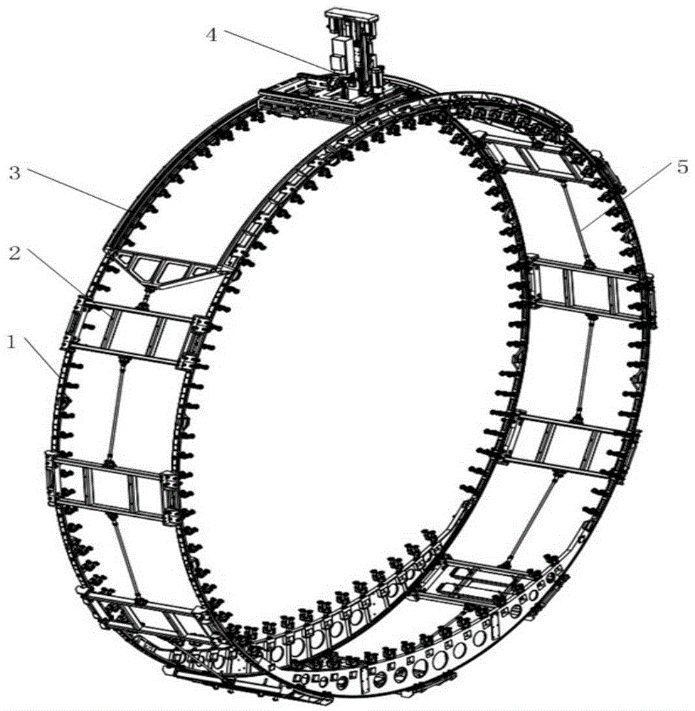
[0060] Such as figure 1 As shown, the hole-making device of this embodiment includes: an annular track module 1 , a track cage module 2 , an arc-shaped track module 3 , an automatic hole-making unit 4 and a cage link (link) 5 . The circular track module 1 is placed outside the aircraft fuselage, and the track holder module 2 is used to maintain the shape of the circular track module 1, and is connected with the arc track module 3 to form a ring around the circular track module 1, which is automatically made The hole unit 4 is slidingly fitted on the arc track module 3 .

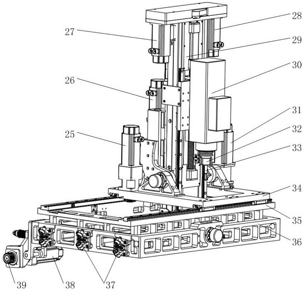
[0061] Such as figure 2 As shown, the automatic hole making unit 4 includes: Y-axis servo motor 25, B-axis servo motor 26, Z1-axis servo motor 27, Z2-axis servo motor 28, intermediate pallet 29, electric spindle 30, A-axis servo motor 31, fast Tool changing handle 32, cutting tool 33, ...


PUM


Abstract

The invention discloses a method for acquiring joint variables by inversely solving a kinematical equation of an annular track hole making system. According to the method, due to the fact that an annular track is complex in structure and has a plurality of numerical control movement axes and the characters of rectilinear motion and axis-around swing, a mechanical model of the annular track hole making system is established, the transformation matrixes of all connecting rods are determined based on the mechanical model, the kinematical equation is obtained according to the transformation matrixes and the homogeneous transformation multiplication rule, the algebraic method is adopted to solve the kinematical equation, and the joint variables are obtained. The corresponding joint parameters can be inversely solved according to the given target poses, motion control of the annular track hole making system is achieved, an inverse solution algorithm is provided for automatic control system software programming of the annular track hole making system, the method is the basis of the automatic system control theory, and the hole making efficiency and precision of the whole system are greatly improved.

Description

technical field [0001] The invention relates to the field of automatic hole-making for aircraft digital assembly, in particular to a method for obtaining joint variables by inversely solving the kinematic equation of a ring-track hole-making system. Background technique [0002] Aircraft assembly is the main link in the aircraft manufacturing process. The aircraft assembly workload accounts for about 40% to 50% of the entire aircraft manufacturing workload. The assembly workload mainly consists of hole making, countersinking and riveting. The problem of precise hole making of large aircraft parts has always been a thorny problem in the aviation industry, and so far there is no completely satisfactory solution for various structural parts. [0003] Taking the assembly of the docking section of the fuselage of a large aircraft as an example, the number of machining holes is huge in the annular area of ​​the docking section. As the proportion of difficult-to-machine materials s...

Claims


Application Information

Patent Timeline
IPC IPC(8): G05B19/19
Inventor 曲巍崴方垒董辉跃柯映林
Owner ZHEJIANG UNIV
Learn More