Laser sterilizing and pest control method and device
An insect-killing and laser technology, which is applied to devices for capturing or killing insects, animal husbandry, applications, etc., can solve the problems of increasing equipment costs, long-term work, adverse environmental effects, etc., and achieves low equipment manufacturing costs and long service life. Long, fast scan effects
- Summary
- Abstract
- Description
- Claims
- Application Information
AI Technical Summary
Problems solved by technology
Method used
Image
Examples
Embodiment 1
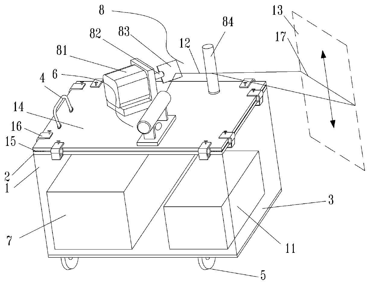
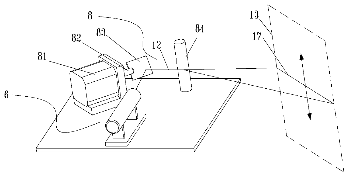
[0034] like figure 1As shown, the moving mechanism in this example adopts a small hand-held four-wheeled cart commonly used in hospitals, including a moving mechanism box 1 , a partition 2 , a bottom plate 3 , a handle 4 , and casters 5 . Both the laser 6 and the optical path guiding system 8 are relatively fixed on the supporting plate 14, and then the supporting plate 14 is placed on the partition 2 and fixed by the quick fixing device 16. In this embodiment, a quick fixing clip is used. , when in use, connect the supporting plate 14 and the partition plate 2 through a ㄩ-shaped clip body, and then tighten the upper hand screw until the hand screw presses the supporting plate 14. The four corners and the bottom of the middle position of the supporting plate 14 are provided with shock-absorbing and anti-skid members 15, and rubber gaskets are used in this embodiment. The laser high voltage power supply 7 and the optical path guiding system power supply 11 are placed on the ba...
Embodiment 2
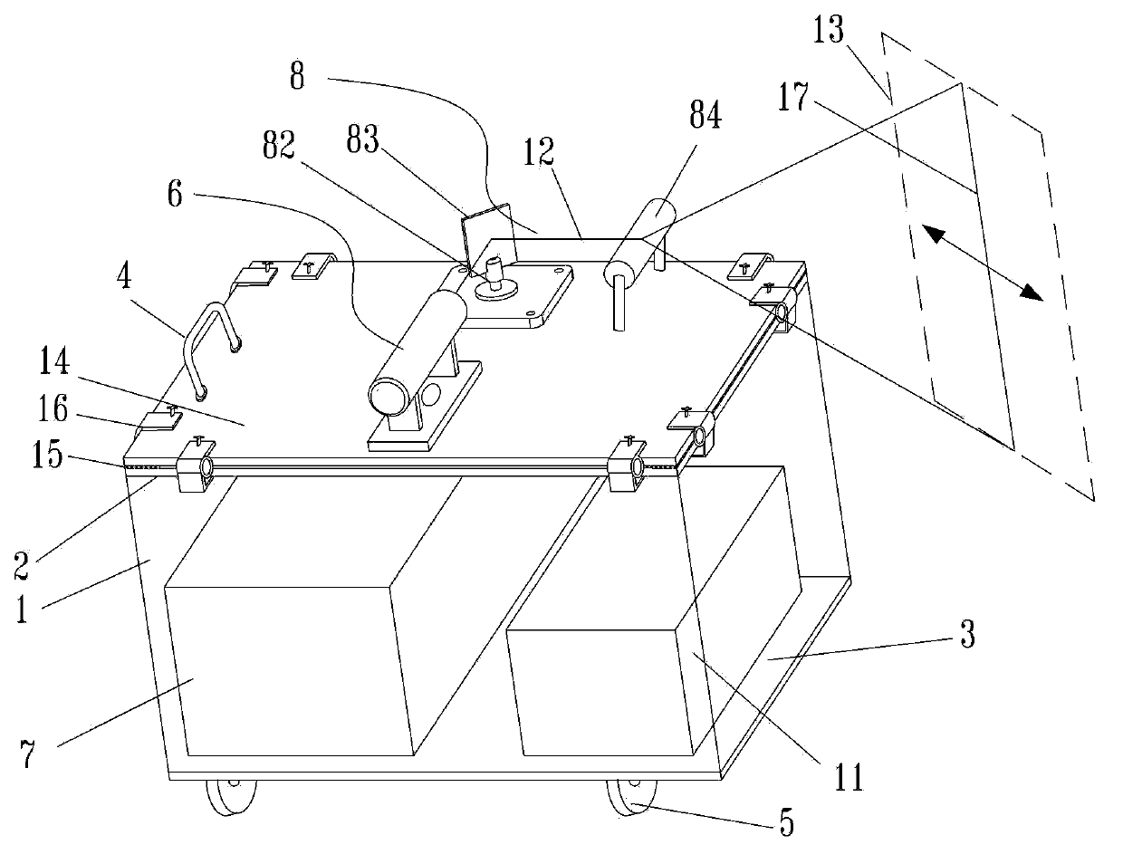
[0039] like image 3 , Figure 4 As shown, the laser 6 is a carbon dioxide laser, which outputs an infrared laser with a Gaussian distribution with a wavelength of 10.6 microns, a pulse peak power of 200 W, a pulse frequency of 5 khz, and a pulse width of 0.5 ms. The cylindrical lens 84 is placed parallel to the horizontal plane, and the reflected laser beam will expand into a line light source 17 perpendicular to the horizontal plane after passing through the cylindrical lens 84 . The motor 81 is fixed under the partition plate 2 (not shown in the figure), and the mirror 83 is driven to rotate around the axis perpendicular to the horizontal plane by the vertically arranged rotating bracket 82, so that the laser beam moves along the axial direction of the cylindrical lens 84, Further, it is transformed into a moving line light source 17 through the lenticular lens 84 to form a reflective scanning light curtain 13 .
[0040] Other structures are the same as in Example 1.
PUM
| Property | Measurement | Unit |
|---|---|---|
| wavelength | aaaaa | aaaaa |
| frequency | aaaaa | aaaaa |
| wavelength | aaaaa | aaaaa |
Abstract
Description
Claims
Application Information
 - R&D
- Intellectual Property
- Life Sciences
- Materials
- Tech Scout
- Unparalleled Data Quality
- Higher Quality Content
- 60% Fewer Hallucinations
Browse by: Latest US Patents, China's latest patents, Technical Efficacy Thesaurus, Application Domain, Technology Topic, Popular Technical Reports.
© 2025 PatSnap. All rights reserved.Legal|Privacy policy|Modern Slavery Act Transparency Statement|Sitemap|About US| Contact US: help@patsnap.com


