Micro Jet Electrode EDM Device

A processing device and electric spark technology, which is applied in the field of micro-jet electrode EDM devices, can solve the problems of time-consuming micro-electrode processing, changes in electrode diameter, and complicated equipment.

Inactive Publication Date: 2016-08-24
XIAMEN UNIV
View PDF8 Cites 1 Cited by
  • Summary
  • Abstract
  • Description
  • Claims
  • Application Information

AI Technical Summary

Problems solved by technology

In micromachining, photolithography, electron beam processing, and micro-EDM are generally used to make fine patterns, but for small-scale experimental research that only requires simple patterns (such as rectangles or straight lines), photolithography requires masks, photolithography, etc. Resist, exposure machine, etc., electron beam requires a vacuum environment, which is very time-consuming and expensive
Micro electric discharge machining has small macro force and low environmental requirements, but it has problems such as time-consuming micro-electrode processing, difficulty in reaching the micro-nano level of electrodes, and changes in electrode diameter caused by electric erosion, which affect machining accuracy.
Chinese patent CN1290583 discloses a method of compensation for EDM electrodes based on numerical control technology. This method first uses the existing CAD / CAM software to generate the numerical control tool path of the machining electrode, and then according to the shaking mode and The amount of shaking, using the corresponding algorithm to compensate the CNC tool path, has the characteristics of simple and reliable implementation, but there are still problems such as difficult machining of electrodes and high cost
This technology has successfully solved the problem of difficulty in making micro-electrodes in micro-EDM, but this technology still has disadvantages such as low processing efficiency, complex equipment, and high cost.

Method used


Image

  • Micro Jet Electrode EDM Device

Examples


Embodiment Construction

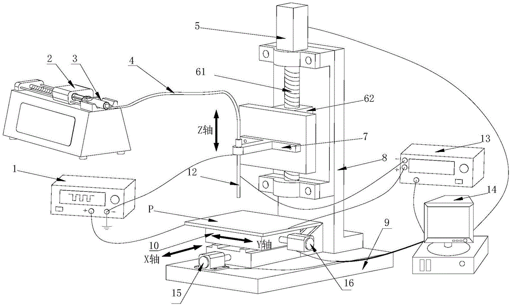
[0010] See figure 1 This embodiment is provided with a pulse signal generator 1, a syringe pump 2, a solution injector 3, a flexible catheter 4, a Z-axis drive motor 5, a feed adjustment device (including a screw 61 and a slider 62), a clamping device 7, Device support 8, base 9, XY motion platform 10, metal needle 12, discharge state detection device 13, X-axis drive motor 15, Y-axis drive motor 16, and computer controller 14.

[0011] The positive pole of the pulse signal generator 1 is connected with the workpiece P to be processed, and the negative pole is connected with the metal needle 12 and grounded; the solution syringe 3 containing the high polymer solution is installed and fixed on the syringe pump 2; the metal needle 12 It is connected to the solution syringe 3 through the flexible catheter 4, and the flow rate of the syringe pump can be set to control the speed of the solution ejected from the needle; the metal needle 12 is axially limited by the stepped hole in the ...


PUM


Abstract

The invention discloses a micro jet flow electrosparking device, and relates to electrosparking devices. A positive electrode of a pulse signal generator is connected with a workpiece, and a negative electrode of the pulse signal generator is connected with a metal syringe needle. A solution injection syringe is fixed to an injection pump. The metal syringe needle is connected with the injection syringe and vertically fixed to a feeding adjusting device through a clamping device. The feeding adjusting device is provided with a lead screw and a sliding block. The lead screw is connected with an output shaft of a Z-axis driving motor. The sliding block is in screw-thread fit with the lead screw. The detection end of a discharging state detection device is connected with the metal syringe needle and a workpiece to be machined. The signal output end of the discharging state detection device is connected with a controller. The feeding adjusting device is fixed to a base. An X-Y motion platform is fixed to the base and used for clamping the workpiece to be machined. An output shaft of an X-axis driving motor is connected with the X-axis direction of the X-Y motion platform. An output shaft of a Y-axis driving motor is connected with the Y-axis direction of the X-Y motion platform. The output end of the controller is electrically and respectively connected with the Z-axis driving motor, the X-axis driving motor and the Y-axis driving motor.

Description

Technical field [0001] The invention relates to electric spark processing equipment, in particular to a fine jet electrode electric spark processing device. technical background [0002] With the continuous development of modern technology, the demand for microelectromechanical systems and large-area flexible thin film devices has exploded. The production of fine patterns in micromachining generally uses photolithography, electron beam machining, and micro-EDM, but for small-scale experimental studies that only require simple patterns (such as rectangles or straight lines), photolithography requires masks, light For resists, exposure machines, etc., electron beams require a vacuum environment, which is time-consuming and costly. Micro-EDM machining has small macro stress and low environmental requirements. However, it has problems such as time-consuming micro-electrode machining, difficulty in reaching the micro-nano level of the electrode, and changes in electrode diameter caus...

Claims


Application Information

Patent Timeline
Patent Type & Authority Patents(China)
IPC IPC(8): B23H1/00B23H9/00
Inventor 吴德志黄少华肖志明郑高峰陈艺慧刘益芳孙道恒
Owner XIAMEN UNIV
Why Eureka
Try Eureka