Electric system state estimation method

A technology of power system and state estimation, applied in system integration technology, information technology support system, computing, etc., can solve problems such as algorithm non-convergence, unreasonable weight distribution, and inability to effectively track transient changes

Active Publication Date: 2014-08-06
SICHUAN HUATAI ELECTRIC
View PDF3 Cites 33 Cited by
  • Summary
  • Abstract
  • Description
  • Claims
  • Application Information

AI Technical Summary

Problems solved by technology

[0004] When a short circuit occurs in the system (three-phase or single-phase ground short circuit, etc.), these algorithms cannot effectively track the transient changes of the voltage or phase angle of each node in the system, especially the voltage or phase angle of the nodes that cannot be directly observed by the PMU. Transient change of phase angle;
[0005] When the system experiences large disturbances (short circuit, load mutation or line parameter error), the robustness of the algorithm is poor, and even the algorithm does not converge;
[0006] The distribution of measurement weights in the algorithm is given according to experience, which cannot reflect the change of measurement error in the dynamic situation of the system, resulting in unreasonable weight distribution and affecting the accuracy of estimation;

Method used


Image

  • Electric system state estimation method
  • Electric system state estimation method
  • Electric system state estimation method

Examples


Embodiment 1

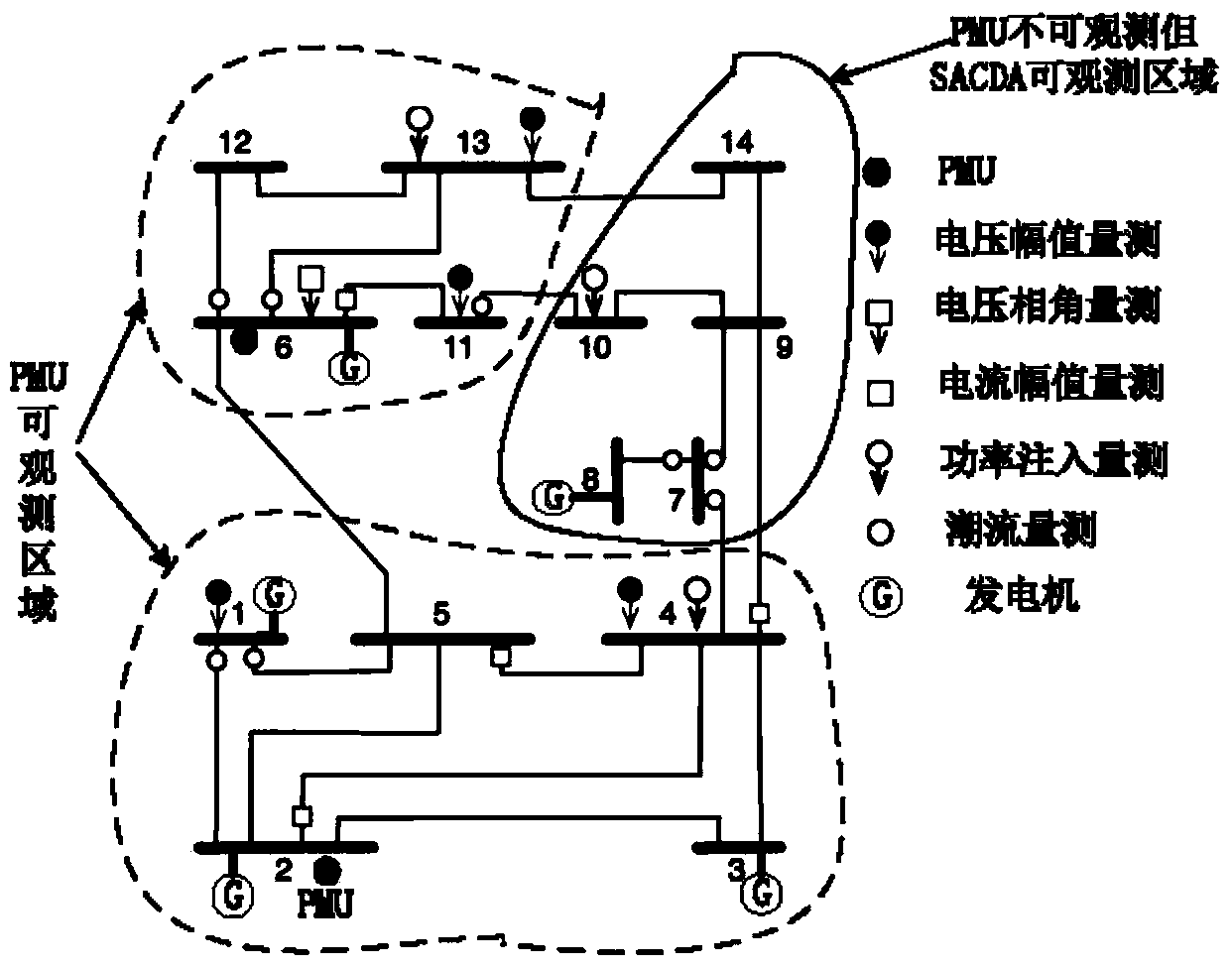
[0103] Embodiment 1: When the IEEE14 system is in stable operation (no sudden change in load, generation of generator and short circuit, etc.), the configuration of SCADA and PMU is as attached figure 2 shown. In this example, the SACDA data comes from the traditional fast power flow calculation results, while the PMU measurement data is generated by the time-domain transient analysis software PSAT. In addition, in order to reflect the actual application situation, a random Gaussian white noise with a mean value of 0 and a variance of 0.02 is added to the power in the SCADA measurement (active and reactive power injection measurement, active and reactive power flow measurement), while for the voltage Random Gaussian white noise with a mean of 0 and a variance of 0.01 was added to the measurement. The IEEE14 node system is fully observable under SCADA measurement, but some nodes are not observable when only PMU is configured, that is, nodes 7, 8, 9, 10, and 14 are completely ...

Embodiment 2

[0105] Embodiment 2: The experimental parameters and platform are consistent with the situation 1, but a three-phase ground fault (0.1s) occurs at the node of the IEEE14 node, Figure 7 The voltage tracking situation of nodes 14, 13, 10 and 9 within 1s is given. It can be seen from the figure that the present invention can track the voltage change of the system well when the system changes dynamically, and after the fault is cleared , the method can also quickly track the new operating point of the system, which shows that the method of the present invention has better robustness.

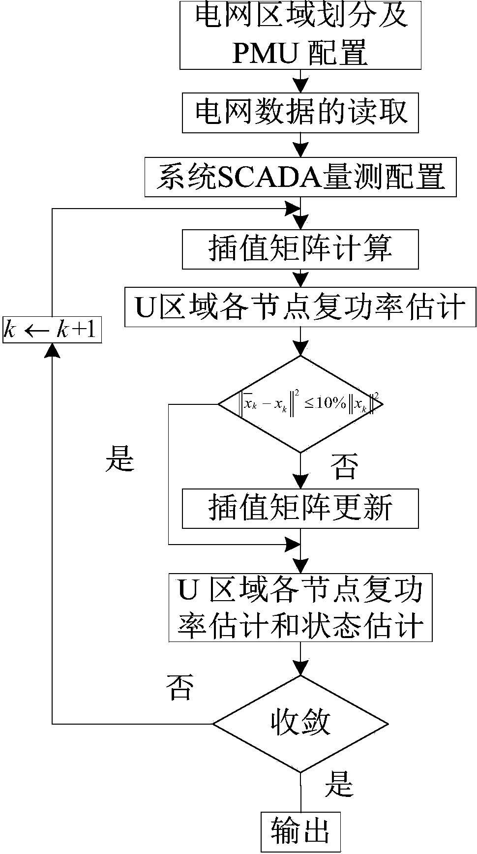
[0106] In summary, the present invention can pass through the interpolation matrix based on node admittance matrix transformation no matter the system is in a steady state operation or experiences a disturbance, and the real-time operating state (voltage and phase angle) of the system that cannot be directly observed by the PMU but can be observed by the SCADA ) is calculated by the real-time volta...


PUM


Abstract

The invention belongs to the technical field of electric system operation and control, and particularly relates to an electric system state estimation method of a Phasor Measurement Unit-PMU based on an interpolation matrix. According to the method, during the updating interval period of SCADA measurement, a state, obtained through a PMU interpolation, of an area U is equivalent to prior state information of the area U, the prior state information is continuously updated at each sampling instant of the PMU, the interpolation matrix is updated when SCADA measurement and PMU measurement reach simultaneously at the next moment, and therefore the real-time running state of each node of the area U is worked out. The method has the advantages of being high in accuracy and sampling speed of PMU measurement, and can track the running state of the system accurately in real time.

Description

technical field [0001] The invention belongs to the technical field of power system operation and control, and in particular relates to a power system state estimation method based on an interpolation matrix and including a phase angle measurement device (Phasor Measurement Unit-PMU). Background technique [0002] Since Schweppe introduced the state estimation into the power system for the first time in 1970, the state estimation of the power system has become an important part of the grid energy management system and the online decision-making stability control system. Injection measurement, active and reactive power flow measurement, voltage and current measurement) to obtain the best estimate of the current state of the system, and provide real-time and accurate operating data for the online analysis and control of the power system. At present, these telemetry data for power system state estimation mainly come from SCADA (Data Acquisition and Supervisory Control System), ...

Claims


Application Information

Patent Timeline
Patent Type & Authority Applications(China)
IPC IPC(8): H02J3/00G06F19/00
CPCY04S10/265Y02E60/728Y02E40/70Y02E60/00Y04S10/00Y04S10/22
Inventor 张葛祥赵俊博
Owner SICHUAN HUATAI ELECTRIC
Why Eureka
Try Eureka