

Method for improving cooling effect of pure aluminum cooling fin
A technology of heat dissipation effect and heat sink, which is applied in nanotechnology, nanotechnology, nanotechnology and other directions for material and surface science, can solve the problems of increasing production cost, increasing the size of the heat sink, and being small in size, and achieves an increase in size. The effect of heat dissipation capacity, enhanced heat dissipation capacity, and simplified production process
- Summary
- Abstract
- Description
- Claims
- Application Information
AI Technical Summary
Problems solved by technology
Method used
Image

Examples
Embodiment 1
[0034] A method for improving the heat dissipation effect of a pure aluminum heat sink, the specific steps are as follows:
[0035] Step A: use deionized water (resistivity 10MΩ·cm) and oxalic acid to prepare a 0.3mol / L oxalic acid solution as an electrolyte, and place the electrolyte in an ice-water bath to control the temperature of the electrolyte at 5°C;
[0036] Step B: Clean the pure aluminum heat sink with ethanol (analytical grade), and dry it naturally;
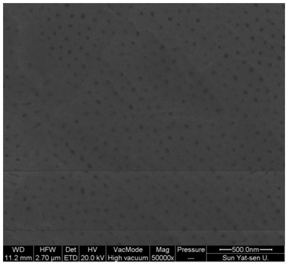
[0037] Step C: use the pure aluminum heat sink treated in step B) as the anode, the graphite electrode as the cathode, and the oxalic acid solution in step A) as the electrolyte, and anodize under DC voltage for 40 minutes until the surface of the heat sink forms a pore size of 20-100nm , A porous alumina layer with a thickness of 7-12 μm.
Embodiment 2
[0039] A method for improving the heat dissipation effect of a pure aluminum heat sink, the specific steps are as follows:
[0040] Step A: use deionized water (resistivity 15MΩ·cm) and oxalic acid to prepare a 0.4mol / L oxalic acid solution as an electrolyte, and place the electrolyte in an ice-water bath to control the temperature of the electrolyte at 8°C;
[0041] Step B: Clean the pure aluminum heat sink with ethanol (analytical grade), and dry it naturally;
[0042] Step C: use the pure aluminum heat sink treated in step B) as the anode, the graphite electrode as the cathode, and the oxalic acid solution in step A) as the electrolyte, and anodize under DC voltage for 40 minutes until the surface of the heat sink forms a pore size of 20-100nm , A porous alumina layer with a thickness of 7-12 μm.
Embodiment 3
[0044] A method for improving the heat dissipation effect of a pure aluminum heat sink, the specific steps are as follows:
[0045] Step A: use deionized water (resistivity 20MΩ·cm) and phosphoric acid to prepare an oxalic acid solution with a concentration of 0.5mol / L as the electrolyte, and place the electrolyte in an ice-water bath to control the temperature of the electrolyte at 10°C;
[0046] Step B: Clean the pure aluminum heat sink with ethanol (analytical grade), and dry it naturally;
[0047] Step C: use the pure aluminum heat sink treated in step B) as the anode, the graphite electrode as the cathode, and the oxalic acid solution in step A) as the electrolyte, anodize under DC voltage for 50 minutes until the surface of the heat sink forms a pore size of 20-100nm , A porous alumina layer with a thickness of 7-12 μm.
[0048] figure 1 It is a surface electron microscope image of the heat sink processed by the method of the above-mentioned embodiment 2. It can be seen ...
PUM
| Property | Measurement | Unit |
|---|---|---|
| Aperture | aaaaa | aaaaa |
| Thickness | aaaaa | aaaaa |
| Thickness | aaaaa | aaaaa |
Abstract
Description
Claims
Application Information