Annular cylinder engine

An engine and ring cylinder technology, applied in the engine field, can solve the problems of low efficiency, unreasonable structure and heavy weight of piston engines, and achieve the effects of high efficiency, simplified engine structure, and low power consumption

Inactive Publication Date: 2014-08-13
苗军
View PDF5 Cites 2 Cited by
  • Summary
  • Abstract
  • Description
  • Claims
  • Application Information

AI Technical Summary

Problems solved by technology

[0003] The purpose of the present invention is to overcome the defects of large volume, heavy weight and low efficiency caused by the unreasonable structure of the piston engine, and provide a ring cylinder engine

Method used


Image

  • Annular cylinder engine
  • Annular cylinder engine
  • Annular cylinder engine

Examples


Embodiment 1

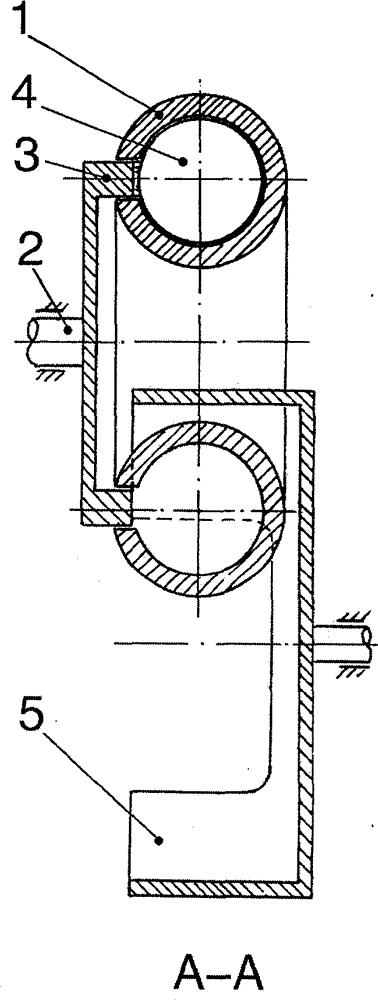
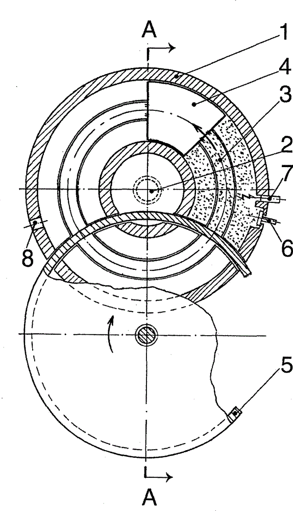
[0023] Such as figure 1 , figure 2 As shown, in the annular cylinder engine of the present invention, the center of the annular cylinder 1 is provided with a main shaft 2 and a cylindrical hub 3 thereof, and the mouth end of the hub is cut from the side of the annular cylinder to its inner cavity and is affixed to the rotary piston 4 therein. , to form a ring cylinder assembly, the inner and outer walls of the hub are in sealing and dynamic fit with the cut part of the ring cylinder, the rotating shaft is parallel to the main shaft, and the rotary drum 5 with a notch on the wall cuts into the ring cylinder from the opposite side of the hub until Its mouth end sticks to the mouth end of the shaft hub and performs a sealing and dynamic fit. The outer wall of the drum is sealed and dynamically fit with the cut part of the annular cylinder. On the outer side of the two cuts cut by the ring cylinder by the drum, an intake valve 6, Exhaust port 8, both counter-rotating pistons are...

Embodiment 2

[0025] Such as Figure 7 As shown, according to Embodiment 1, an annular cylinder assembly is provided around the drum 5, and the outer wall of the drum and the cut parts of the annular cylinders 1, the mouth end of the drum and the mouth ends of the hubs 3 are sealed and dynamically fitted. .

Embodiment 3

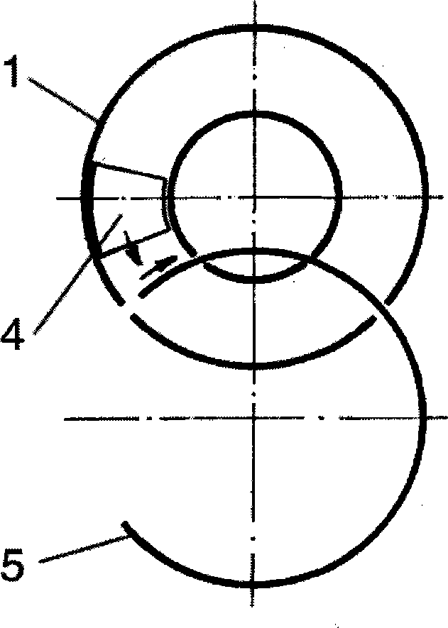
[0027] Such as Figure 8 As shown, according to Embodiment 1, two ring cylinder assemblies are arranged on the periphery of the rotating drum 5, and the outer wall of the rotating drum and the cut parts of each annular cylinder 1, the mouth end of the rotating drum and the mouth ends of each hub 3 are sealed dynamic. Cooperate.


PUM


Abstract

The invention discloses an annular cylinder engine. The annular cylinder engine is characterized in that a main shaft (2) is arranged at the center of an annular air cylinder (1) which is internally provided with a rotary piston (4), a shaft hub (3) of the main shaft is in sealing movable fit with the annular air cylinder by cutting in the side surface of the annular air cylinder, the opening end of the shaft hub is fixedly connected with the rotary piston, and a rotary drum (5) which is parallel to the main shaft and is provided with a notch is in sealing movable fit with the opening end of the shaft hub by cutting in the annular air cylinder from an opposite side of the shaft hub until the opening end of the rotary drum is attached to the opening end of the shaft hub and is in sealing movable fit with the opening end of the shaft hub; the rotary drum and the rotary piston are reversely rotated at the same speed, the notch of the rotary drum is rotated into an inner cavity of the annular air cylinder at the right moment, the notch of the rotary drum is rotated out of the inner cavity of the annular air cylinder after the rotary piston penetrates through the notch in a barrier-free way, the inner cavity is sealed by the wall of the rotary drum, a sealed combustion chamber is formed by enclosing the tail end of the rotary piston, the inner cavity of the annular air cylinder, the outer wall of the rotary drum and the opening end of the shaft hub at the moment, flammable gas is sprayed in a gas inlet (6), combustion is carried out by igniting an ignition plug (7), the rotary piston and the main shaft are pushed to do work in a circulation rotating way, and waste gas is exhausted by a gas exhaust outlet (8). The annular cylinder engine disclosed by the invention can be connected with various machines in parallel and in series, the size is small, the weight is light, and high efficiency and energy saving are realized.

Description

[0001] Technical field: the present invention relates to an engine, in particular to a ring-cylinder engine. Background technique [0002] The piston engine has many reciprocating parts, and the volume and mass of the crank-link mechanism are large, resulting in large inertia, high power consumption, large vibration, and fast wear. The crankshaft only performs work once every two weeks, and the efficiency is low and unstable. For overcoming its deficiency, people want to develop rotary engine (Rotary Engine) always for many years, and the various schemes that come out all fail because of various problems. Later, a "Wankel Rotary Engine" (Wankel Rotary Engine) appeared, but because the air-tight strip at the top of the rotor is in line contact with the inner wall of the engine casing, the seal is poor, the stress is large, the wear is fast, and the efficiency declines quickly, so currently only Japan The Mazda company carries them on individual sports cars. Through extensive s...

Claims


Application Information

Patent Timeline
Patent Type & Authority Applications(China)
IPC IPC(8): F02B53/00F02B55/08F02B55/14F02B53/02F02B75/18
CPCY02T10/17Y02T10/12
Inventor 苗军
Owner 苗军
Why Eureka
Try Eureka