Composite measurement system and measurement method for micro-array complex surface optical element
A technology of complex curved surfaces and optical components, applied in the field of microstructure topography testing, can solve the problems of lack of testing methods, short time, low device yield and reliability, etc., to expand the measurement range, improve the measurement speed, and improve the measurement accuracy. Effect
- Summary
- Abstract
- Description
- Claims
- Application Information
AI Technical Summary
Problems solved by technology
Method used
Image

Examples
Embodiment Construction
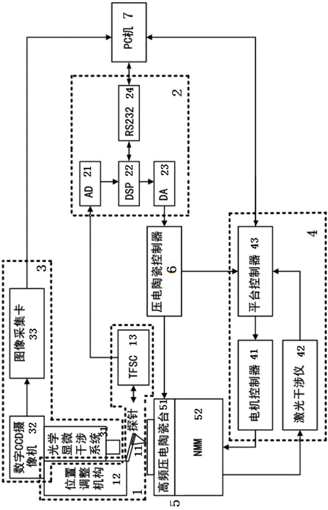
[0042] The compound measuring system and measuring method of the microarray type complex curved surface optical element of the present invention will be described in detail below in combination with the embodiments and the accompanying drawings.
[0043] The composite measuring system of the microarray complex curved surface optical element of the present invention combines the optical micro-interference technology and the scanning probe technology, and the cantilever beam probe adopts the new self-excitation / self-induction tuning fork probe Akiyama probe from the Swiss Nanosensors company. Needle, without the traditional optical signal detection part, design a compact probe, build a new measurement system, so as to realize the combination of optical measurement and mechanical measurement, the combination of non-contact measurement and contact measurement, the combination of full-field measurement and single-point measurement The combination of scanning measurement combines the...
PUM
 Abstract
Description
Claims
Application Information
 - Generate Ideas
- Intellectual Property
- Life Sciences
- Materials
- Tech Scout
- Unparalleled Data Quality
- Higher Quality Content
- 60% Fewer Hallucinations
Browse by: Latest US Patents, China's latest patents, Technical Efficacy Thesaurus, Application Domain, Technology Topic, Popular Technical Reports.
© 2025 PatSnap. All rights reserved.Legal|Privacy policy|Modern Slavery Act Transparency Statement|Sitemap|About US| Contact US: help@patsnap.com