Method for designing dielectric reflector antenna

A design method and reflective surface technology, applied to antennas, electrical components, etc., can solve the problems of low antenna efficiency, complex design of parabolic antenna surface, complex processing and installation, etc., and achieve high gain effect

Inactive Publication Date: 2014-08-13
XIDIAN UNIV
View PDF3 Cites 17 Cited by
  • Summary
  • Abstract
  • Description
  • Claims
  • Application Information

AI Technical Summary

Problems solved by technology

[0006] The purpose of the embodiments of the present invention is to provide a design method for a dielectric reflector antenna, which aims to solve the problem of complex feed network, large feed loss, and low antenna efficienc

Method used


Image

  • Method for designing dielectric reflector antenna
  • Method for designing dielectric reflector antenna
  • Method for designing dielectric reflector antenna

Examples


Embodiment Construction

[0034] In order to make the object, technical solution and advantages of the present invention more clear, the present invention will be further described in detail below in conjunction with the examples. It should be understood that the specific embodiments described here are only used to explain the present invention, not to limit the present invention.

[0035] The application principle of the present invention will be further described below in conjunction with the accompanying drawings and specific embodiments.

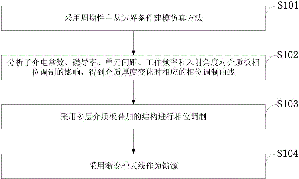
[0036] Such as figure 1 As shown, the design method of the dielectric reflector antenna in the embodiment of the present invention includes the following steps:

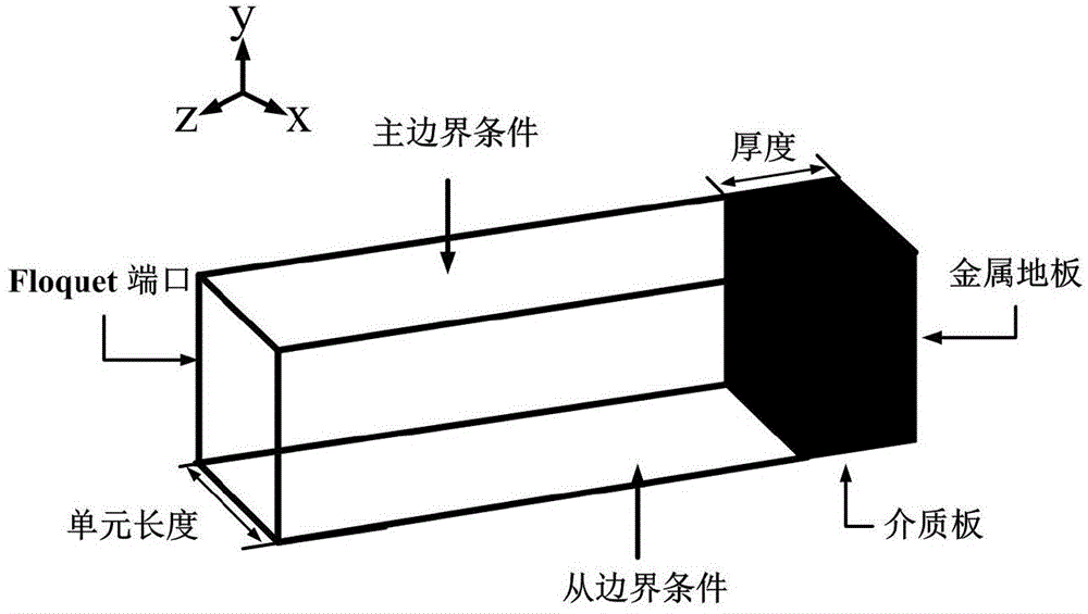
[0037] S101: Adopt periodic master-slave boundary condition modeling and simulation method;

[0038] S102: Analyze the influence of dielectric constant, magnetic permeability, unit spacing, operating frequency and incident angle on the phase modulation of the dielectric plate, and obtain the correspon...


PUM


Abstract

The invention discloses a method for designing a dielectric reflector antenna. The dielectric reflector antenna is composed of a feed source and multiple layers of plane dielectric slabs. Phase modulation is conducted on an array face, wide angular domain beams emitted by the feed source are clustered and reflected to form narrow beams, and therefore high gain is achieved; a periodical master-slave boundary condition modeling and simulating method is adopted; influence on dielectric slab phase modulation by a dielectric constant, the magnetic conductivity, the unit gap, the operating frequency and the incident angle is analyzed, and a corresponding phase modulation curve is obtained when the thickness of dielectric changes; a structure of stacking the dielectric slabs is adopted for phase modulation; a tapered slot antenna is adopted as the feed source. An empty feeding mode is adopted and a design procedure of the dielectric reflector antenna is simplified; the dielectric reflector antenna is formed by stacking the dielectric slabs, no metal patch is arranged, surface loss is reduced, and the efficiency of the dielectric reflector antenna is improved. The dielectric reflector antenna is simple in structure, small in size, low in weight and capable of facilitating processing and installing and has the advantages of being low in loss, high in gain, low in sidelobe and wide in frequency band.

Description

technical field [0001] The invention belongs to the technical field of high-gain antennas, in particular to a design method of a dielectric reflector antenna. Background technique [0002] There are mainly two types of existing high-gain antennas, one is an array antenna, and the other is a reflector antenna. [0003] The array antenna is a combination of multiple antennas distributed according to a certain amplitude and phase. This combination of antennas excites multiple radiating elements, thereby achieving better high gain. The excitation amplitude and phase of each radiation unit are controlled by the feed network. Generally, the higher the gain requirement of the antenna signal, the more the number of radiation elements required, which leads to the more complex feed network. On the one hand, a complex feed network will increase the difficulty of electrical design and physical layout, resulting in adverse effects in terms of structure and weight; on the other hand, co...

Claims


Application Information

Patent Timeline
IPC IPC(8): H01Q19/10H01Q15/14
Inventor 王超陈蕾刘淑芳郭洧华史小卫
Owner XIDIAN UNIV
Why Eureka
Try Eureka