
Digital modulation signal source based on microwave photon technology

A digital modulated signal, microwave photonic technology, applied in electromagnetic wave transmission systems, electrical components, transmission systems, etc., can solve the problems of restricting the development of high-speed dynamic networks, poor tunability, etc., to achieve multiple functions, high flexibility, and tunable range. big effect

Inactive Publication Date: 2014-08-13
闫连山 +1
View PDF3 Cites 2 Cited by
  • Summary
  • Abstract
  • Description
  • Claims
  • Application Information

AI Technical Summary

Problems solved by technology

In schemes (2) and (3), due to the limitation of spectral shaping, only one modulation mode signal can be generated, which is not suitable for the adjustable generation of multiple modulation mode signals, which limits the development of high-speed dynamic networks
[0004] The above three schemes all realize the generation of millimeter-wave digital modulation signals. In scheme (1), the generation of different digital modulation signals can be realized by changing the optical modulation method, but an external microwave carrier signal is required, and the adjustability is poor; (2) and (3) are both based on frequency domain to time domain conversion technology to generate digital modulation signals, which can realize a wide range of adjustable carrier frequency and duty cycle, but due to the limitation of spectral shaping technology can only generate Single modulation digital modulation signal

Method used


Image

  • Digital modulation signal source based on microwave photon technology
  • Digital modulation signal source based on microwave photon technology
  • Digital modulation signal source based on microwave photon technology

Examples


Embodiment Construction

[0018] The present invention will be further described below in conjunction with the accompanying drawings.

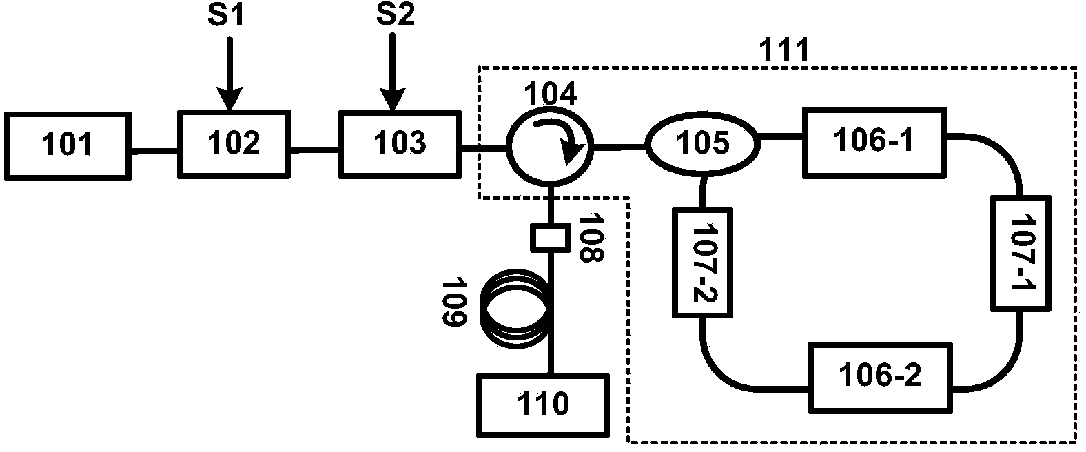
[0019] like figure 1 Shown, the present invention scheme consists of mode-locked laser 101, optical intensity modulator 102, optical polarization modulator 103, tunable polarization-dependent optical comb filter 111, tunable optical bandpass filter 108, linear dispersive medium 109 and optoelectronic The detection unit 110 is constituted. Wherein, the tunable polarization-dependent optical comb filter 111 includes an optical circulator 104, a polarization beam splitter 105, programmable polarization mode dispersion units 106-1, 106-2, 45-degree Faraday rotators 107-1, 107- 2.

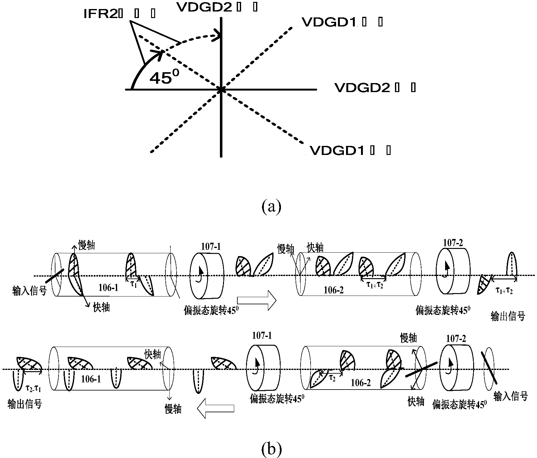
[0020] figure 2 It is a specific implementation of the tunable polarization-dependent optical comb filter 111, in which a 45-degree Faraday rotator is used to rotate the polarization state of the forward and reverse signals by +45 0 , the role of the Faraday rotator 107-1 in Figure (a). At...


PUM


Abstract

The invention discloses a digital modulation signal source based on a microwave photon technology. In a digital modulation signal source composed of a mode locked laser 101, a luminous intensity modulator 102, a light polarization modulator 103, a tunable polarization correlation light comb filter 111, a tunable light band pass filter 108, a linearity dispersion medium 109 and a photoelectric detection unit 110, the tunable polarization correlation light comb filter 111 is formed by connecting a light circulator 104, a polarization beam splitter 105, programmable polarization mold dispersion units 106-1 and 106-2, and 45-degree Faraday rotators 107-1 and 107-2 in a specific mode, such that independent tunable comb filtering can be performed on mutually vertical linear polarization states, digital modulation signals with different modulation rates, different carrier wave frequencies, different modulation modes and different duty ratios are generated, and the digital modulation signal source can be applied to multiple important fields such as the transmitting end of a super-speed network, a radio-on-fiber system, a military radar and the like.

Description

technical field [0001] The invention relates to the technical field of optical devices, in particular to a digital modulation signal source based on microwave photon technology. Background technique [0002] The use of optical methods to generate microwave signals (especially higher frequency millimeter waves) is a research topic that has recently attracted attention. It can not only generate millimeter waves for optical wireless systems, but also generate near-infrared signals with a frequency up to THz for military radar, imaging detection, etc. The microwave signal is generated by the optical method, which not only breaks through the electronic bottleneck, but also has the advantages of anti-electromagnetic interference, wide range of tunability, low loss, and wide bandwidth. On the other hand, the digital modulation signal source refers to the equipment used to generate digital modulation signals. Commonly used digital modulation signals include binary amplitude modulat...

Claims


Application Information

Patent Timeline
IPC IPC(8): H04B10/516
Inventor 姜恒云闫连山潘伟罗斌邹喜华叶佳
Owner 闫连山
Learn More