
Improved nitric acid production

A nitric acid, production process technology, applied to the separation of nitric acid, nitrogen oxides/oxyacids, dispersed particles, etc., to achieve the effect of increasing production

Inactive Publication Date: 2014-08-13
LINDE AG
View PDF6 Cites 4 Cited by
  • Summary
  • Abstract
  • Description
  • Claims
  • Application Information

AI Technical Summary

Problems solved by technology

However, this requires the provision of stand-alone process equipment at a substantial capital investment and will result in scrubber purge streams and wet reactor

Method used


Image

  • Improved nitric acid production
  • Improved nitric acid production
  • Improved nitric acid production

Examples


Embodiment Construction

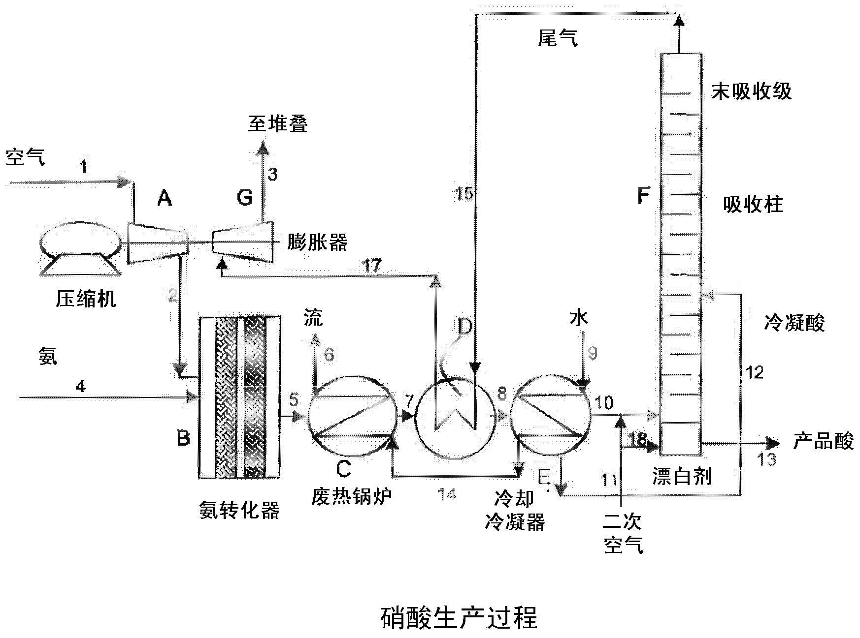
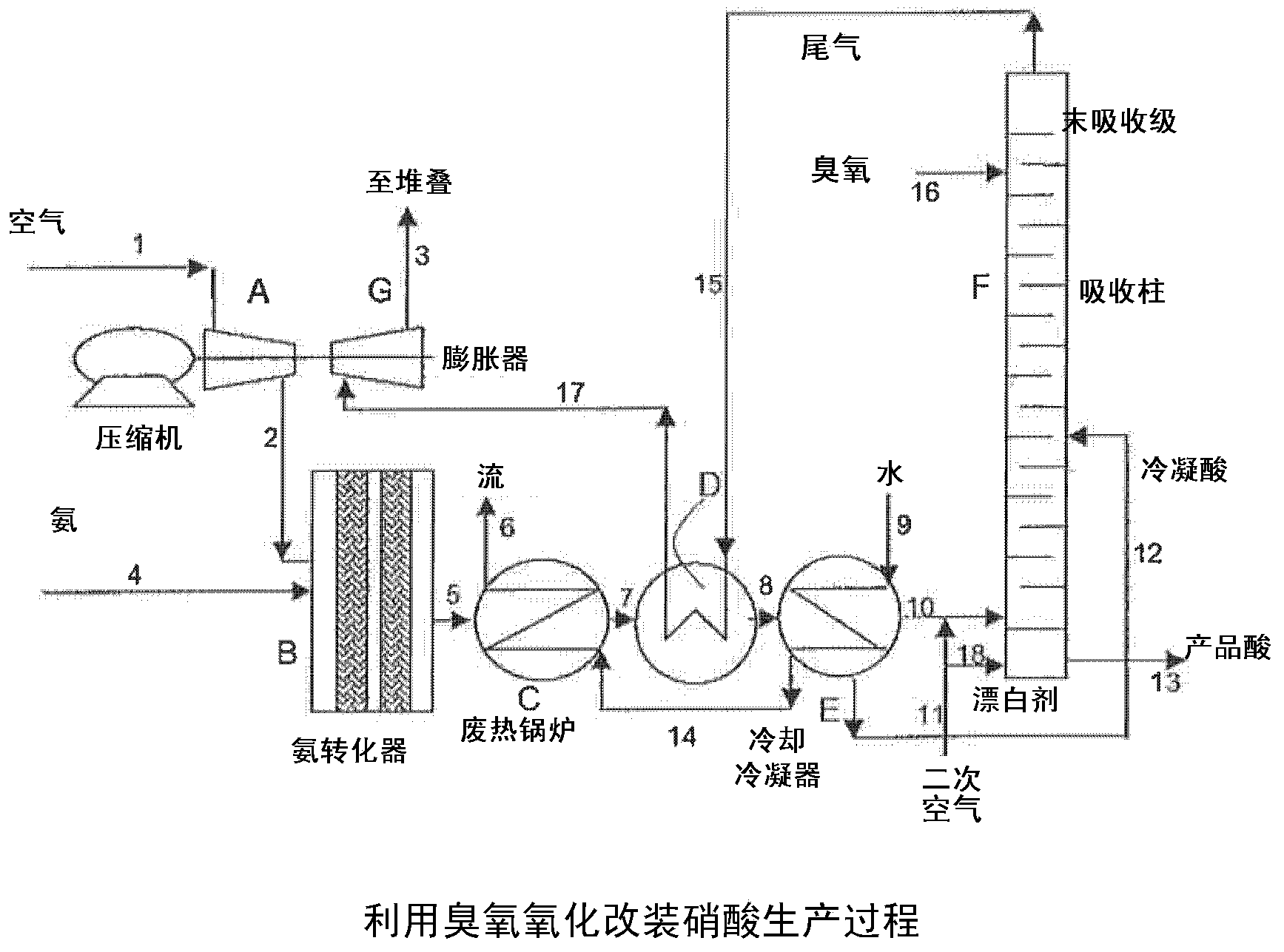
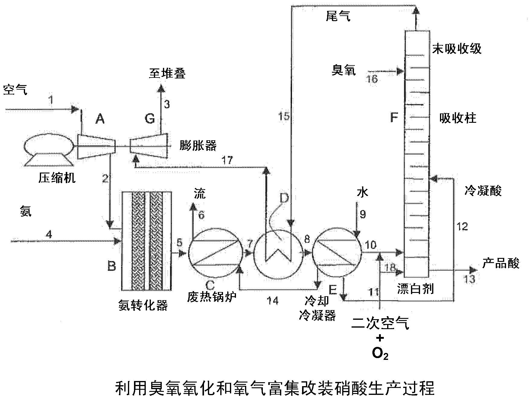
[0036] turn to figure 1, showing a schematic diagram of the nitric acid production process. Air is fed via line 1 to compressor A which feeds compressed air to ammonia converter B via line 2. Ammonia is fed to the premix with air via line 4 and the ammonia is subjected to high temperature oxidation present in ammonia converter B on the surface of the noble metal catalyst. This oxidation reaction is highly exothermic and converts ammonia to nitrogen oxides. The process gas stream leaving ammonia converter B via line 5 consists mainly of nitrogen with residual oxygen, water in vapor form and nitrogen oxides (especially NO). Heat from the process gas stream leaving the ammonia converter is recovered from the waste heat in the waste heat recovery unit C to form a high pressure gas stream in line 6, the tail gas is heated in the heat exchanger D and further eliminated in the cooling condenser E. At this point, the high temperature heat recovered as a gas stream in line 6 can be...


PUM


Abstract

A method for reducing the levels of nitrogen oxides in the tail gas from a nitric acid production process by adding ozone to the absorber column of the production process s disclosed. Nitric acid formation is also intensified by adding a mixture of secondary air and oxygen to the absorber column.

Description

[0001] Cross References to Related Applications [0002] This application claims priority to US Provisional Application No. 61 / 525,899, filed August 22, 2011. Background of the invention [0003] The present invention provides for improved nitric acid production by providing lower nitrogen oxide emissions to the off-gas stream of a nitric acid production process. [0004] Nitric acid is generally produced by high temperature oxidation of ammonia over a noble metal catalyst and air. As the process gas stream cools in the heat recovery plant, the oxidation of ammonia leads primarily to the formation of NO, nitric oxide. During cooling, large amounts of NO are oxidized to NO in the oxygen present in the process gas stream 2 , and some water vapor condenses. In the multiple stages of the absorption plant, the NO and NO 2 The aqueous medium is contacted in a countercurrent fashion to form an aqueous solution of nitric acid. Many reactions occur during cooling, condensation an...

Claims


Application Information

Patent Timeline
Patent Type & Authority Applications(China)
IPC IPC(8): B01D53/56
CPCB01D53/56B01D2251/104B01D53/78C01B21/40Y02P20/129
Inventor N·J·苏查克
Owner LINDE AG
Learn More