Numerical control fuel oil combustion machine and self-inspection method thereof

A digital control, burner technology, applied in the combustion method, control combustion, burner and other directions, can solve the problems of few functions, poor safety, high failure rate, and achieve the effect of overcoming few functions, good safety, and low failure rate

Active Publication Date: 2014-08-27
李延新
View PDF8 Cites 8 Cited by
  • Summary
  • Abstract
  • Description
  • Claims
  • Application Information

AI Technical Summary

Problems solved by technology

[0004] In the process of realizing the present invention, the inventors found that there are at least defects such as few functions, high failure rate and poor security in the prior art

Method used


Image

  • Numerical control fuel oil combustion machine and self-inspection method thereof
  • Numerical control fuel oil combustion machine and self-inspection method thereof

Examples


Embodiment 1

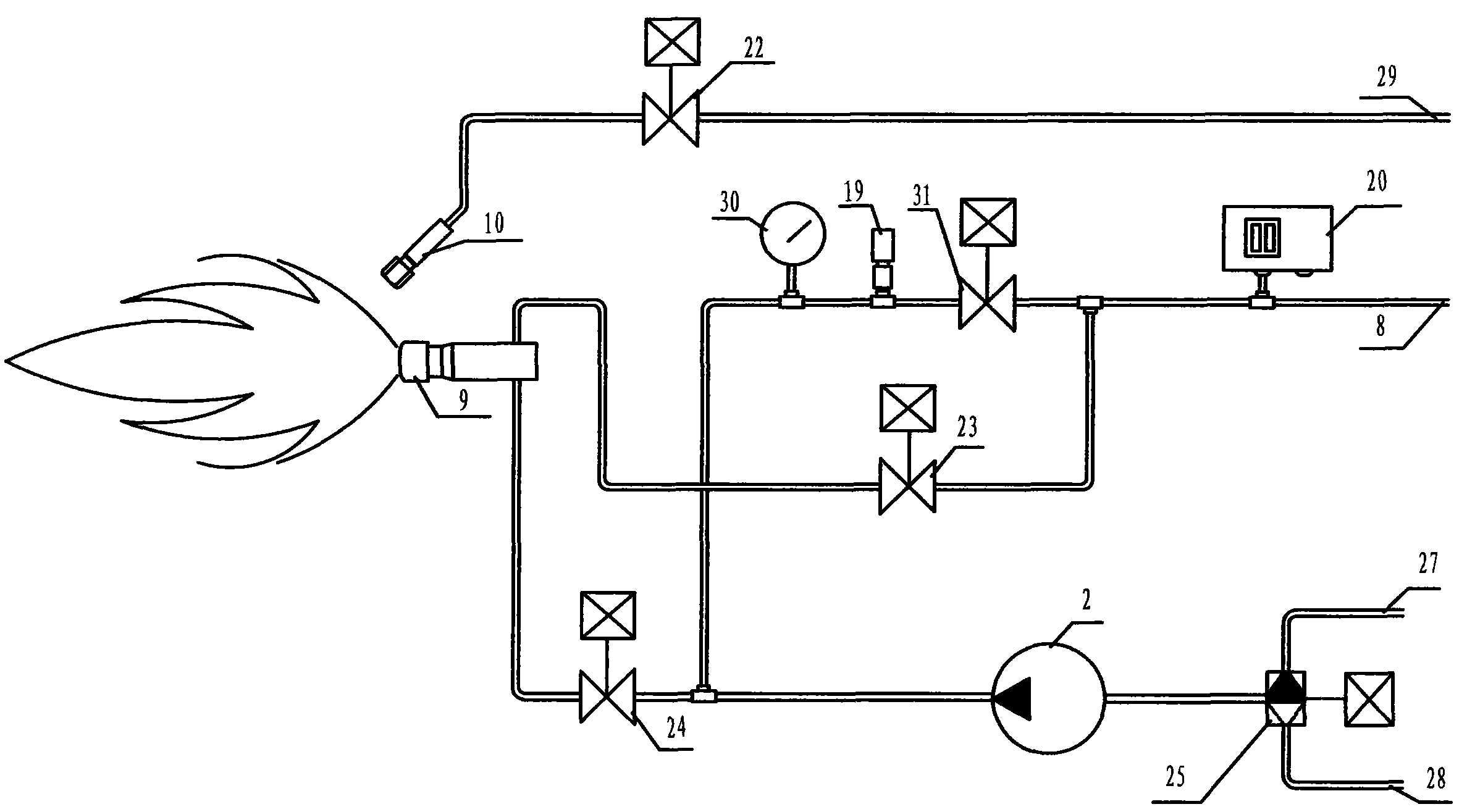
[0055] The digital control fuel burner of this embodiment includes a body, a fuel supply device, an air supply device, a fuel atomization device and an ignition device, and also includes a controller, a motor speed controller and a signal acquisition device; the fuel supply device and the air supply device They are respectively connected to the controller through their respective motor speed controllers, and the signal output terminal of the signal acquisition device is connected to the signal input terminal of the controller. The amount of fuel and the air volume sent by the air supply device.

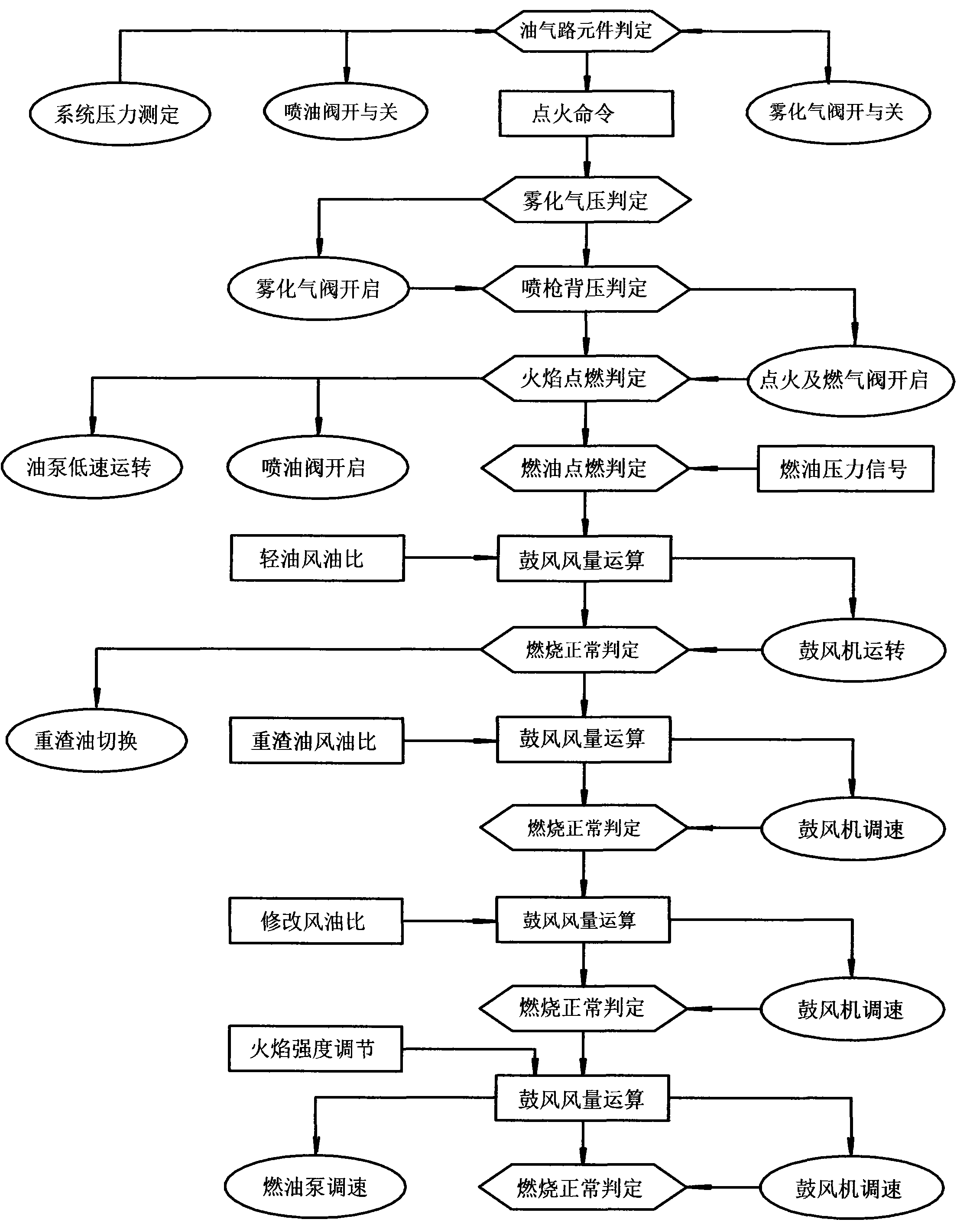
[0056] The above-mentioned controller includes a complete set of fault self-diagnosis program, which further includes:

[0057] a. The function detection program of system components before ignition is used to judge whether the functions of each valve and oil pump are normal before ignition;

[0058] b. The atomization pressure judging procedure before ignition is used to judge wheth...

Embodiment 2

[0069] The self-inspection method of the digital control fuel burner in this embodiment mainly includes the following steps:

[0070] Step 1: Before ignition, judge whether the function of each valve and oil pump is normal according to the opening of the atomizing gas valve and the fuel injection valve and the system pressure in different states;

[0071] The above-mentioned operation of judging whether the functions of each valve and oil pump are normal includes: outputting a certain amount of fuel oil from the fuel supply device to the fuel atomizing device, spraying fuel atomized steam from the fuel atomizing device, and atomizing the fuel oil by the ignition device The steam is ignited, and the air is supplied by the air supply device to assist the combustion;

[0072] If the functions of each valve and oil pump are normal, the output fuel volume and air volume are automatically and synchronously adjusted in proportion by controlling the respective motor speeds of the fuel...


PUM


Abstract

The invention discloses a numerical control fuel oil combustion machine and a self-inspection method thereof. The combustion machine mainly comprises a machine body, a fuel supply device, an air supply device, a fuel oil atomization device, an ignition device, a controller, motor rotating speed controllers and a signal collection device, wherein the fuel supply device, the air supply device, the fuel oil atomization device, the ignition device, the controller, the motor rotating speed controllers and the signal collection device are installed inside the machine body in a matched mode. The fuel supply device and the air supply device are connected with the controller through the motor rotating speed controllers of the fuel supply device and the air supply device. The signal output end of the signal collection device is connected with the signal input end of the controller. The controller automatically, proportionally and synchronously adjusts the fuel oil quantity output by the fuel supply device and the air quantity supplied by the air supply device according to the set air-oil ratio. The numerical control fuel oil combustion machine and the self-inspection method of the numerical control fuel oil combustion machine can overcome the defects that in the prior art, the number of functions is small, the fault rate is high, and safety is poor so as to achieve the advantages that the number of the functions is large, the fault rate is low and the safety is good.

Description

technical field [0001] The invention relates to the technical field of combustion equipment, in particular to a digitally controlled fuel burner and a self-inspection method thereof. Background technique [0002] Due to the simple hardware and control principle of traditional oil and other liquid burners, they only have basic safety protection and ignition and combustion functions. Before starting up, it is not possible to perform fault detection on fuel spray guns, oil and gas circuits, valves and oil pumps. When working for a long time leads to component fatigue or heavy residual oil and other inferior fuels to the pollution and corrosion of the components, the action of the components will fail, often due to oil leakage failure of the fuel injection valve, leading to major vicious accidents of explosion and deflagration. [0003] In order to ensure the safety of people and equipment, the automatic detection of the system before ignition should be very important and necess...

Claims


Application Information

Patent Timeline
Patent Type & Authority Applications(China)
IPC IPC(8): F23D11/00F23D11/36F23N1/02
Inventor 李延新
Owner 李延新
Why Eureka
Try Eureka