

Coated cutting tool
一种切削工具、涂层的技术,应用在涂层、金属材料涂层工艺、制造工具等方向,能够解决脱层、涂层脱层等问题
- Summary
- Abstract
- Description
- Claims
- Application Information
AI Technical Summary
Problems solved by technology
Method used
Image

Examples
Embodiment 1
[0074] A (Ti,Al)N coating was deposited on a S1 substrate in a nitrogen atmosphere using five planar targets, each containing 40 atomic % Ti and 60 atomic % Al.
[0075] Before loading the substrate into the deposition system, the substrate is cleaned by dry blasting for honing to obtain a cutting edge radius of 30-60 μm, followed by wet blasting to remove residues from the dry blasting step. The dry spraying is carried out at a pressure of about 0.4 MPa to 0.6 MPa using a nozzle having a diameter of 10 mm and 100 mesh alumina particles, the nozzle being arranged at a distance of about 150 mm and an angle of about 45° with respect to the rake face of the substrate, i.e., The particles impinge on the rake face of the substrate at an angle of 45°. Wet blasting was performed using a 9.5 mm diameter nozzle and 360 mesh alumina particles at a pressure of about 0.4 MPa, the nozzle being positioned at a distance of about 150 mm and at an angle of about 45° relative to the substrate r...
Embodiment 2
[0081] A (Ti,Al)N coating was deposited on an S2 substrate in a nitrogen atmosphere using five planar targets, each containing 40 atomic % Ti and 60 atomic % Al.
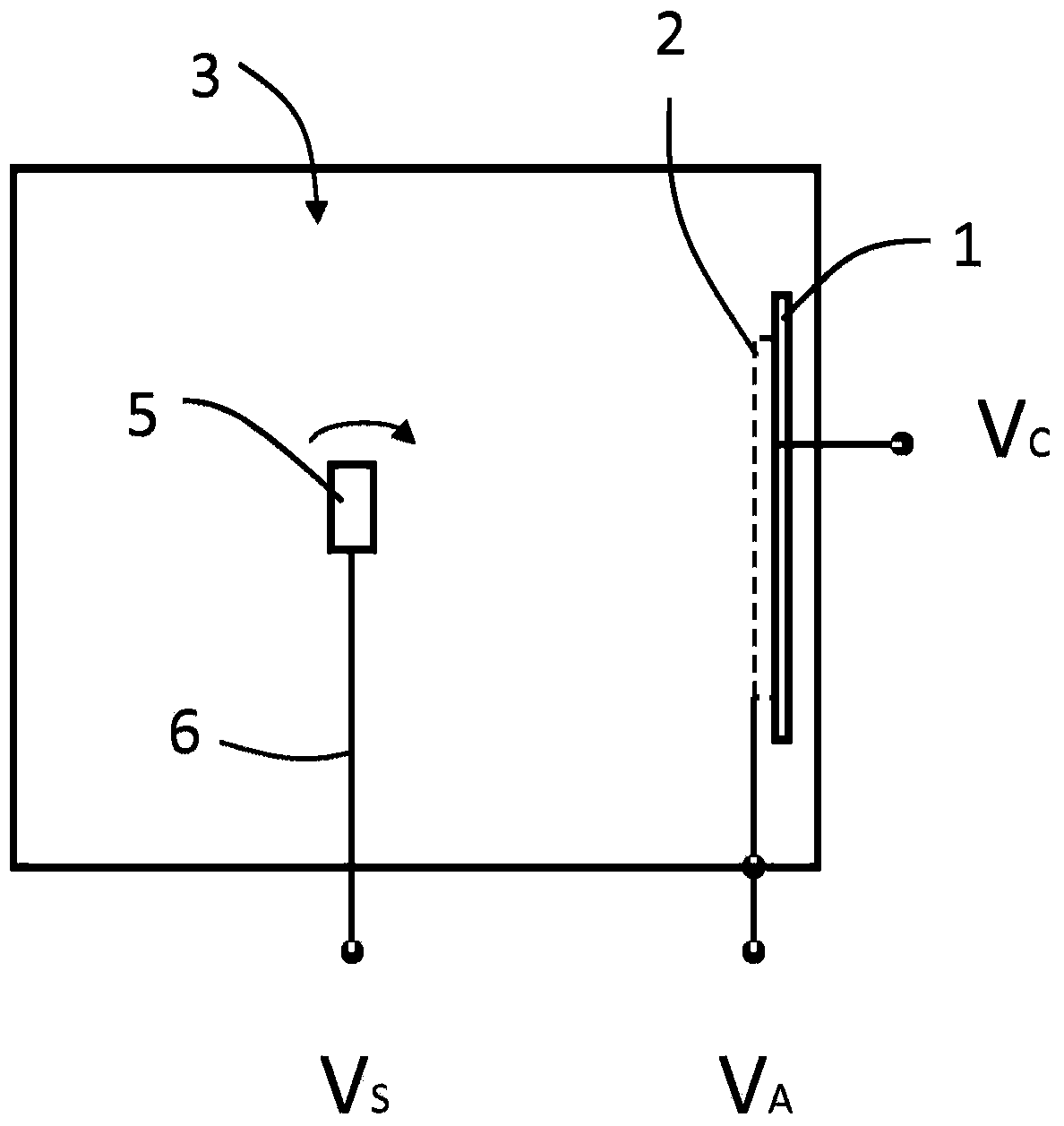
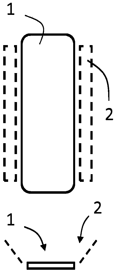
[0082] Before deposition, the substrate was pretreated in the manner of Example 1, placed horizontally and subjected to plasma etching. The coating was deposited using the following deposition conditions: temperature 450°C, nitrogen pressure 5Pa, arc current 400A, bias voltage 35.5V (DC), cathode voltage 17.5V. After deposition, the coating was post-treated in the manner of Example 1.
[0083] The thickness of the coating was 14 μm on the flank and 8 μm on the rake. The hardness is 31GPa. The internal stress after wet spray coating is -1950MPa. The area surface roughness of the coated cutting tools was measured on the rake face using a white light interferometer (Wyko NT9100, Veeco Instruments Ltd). Analysis was performed using a Gaussian bandpass filter rejecting wavelengths greater than 0.08 mm. The arithmeti...
Embodiment 3
[0086] A (Ti,Al)N coating was deposited on a S1 substrate in a nitrogen atmosphere using a flat plate-like target containing 40 atomic % Ti and 60 atomic % Al.
[0087] Before deposition, the substrate was positioned vertically, ie with the rake face facing the flat target, and then pretreated and plasma etched in the same manner as in Example 1. The coating was deposited using the following deposition conditions: temperature 450°C, nitrogen pressure 2.5Pa, arc current 400A, bias voltage 19V (DC), cathode voltage 17.5V. After deposition, the coating was wet-sprayed for about 0.5 minutes at a pressure of about 0.4 MPa using a nozzle with a diameter of 12.5 mm at a distance of about 50 mm from the rake face of the substrate and about 500 mesh alumina particles. 45° angle setting.
[0088] The thickness of the coating was 21 μm on the flank and 24 μm on the rake. The hardness is 27GPa. The internal stress after wet spraying of the coating was +90MPa.
PUM
| Property | Measurement | Unit |
|---|---|---|
| roughness | aaaaa | aaaaa |
| compressive stress | aaaaa | aaaaa |
| compressive stress | aaaaa | aaaaa |
Abstract
Description
Claims
Application Information