A novel electrical discharge machining circuit and machining method capable of realizing multi-point electrical discharge high-speed electrical discharge machining
A technology of electric discharge machining and electric spark, which is applied in the direction of electric processing equipment, circuits, metal processing equipment, etc., can solve the problems of low processing efficiency and slow processing speed of workpieces, achieve simple adjustment, uniform discharge energy, and ensure the effect of restoring insulation
- Summary
- Abstract
- Description
- Claims
- Application Information
AI Technical Summary
Problems solved by technology
Method used
Image
Examples
specific Embodiment approach 1
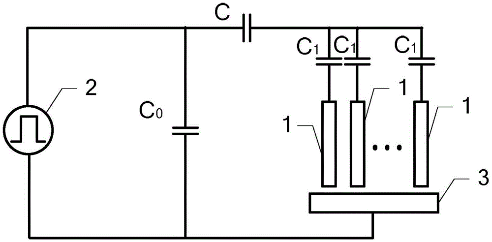
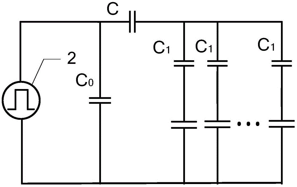
[0030] Specific implementation mode one: see figure 1 and 2Describe this embodiment mode, a new type of electric discharge machining circuit that can realize multi-point discharge high-speed electric discharge machining described in this embodiment mode, it includes N electrodes 1, pulse power supply 2, and N isolation capacitors C 1 , compensation capacitor C 0 , Feeding capacitor C, one end of the N electrodes 1 are respectively connected with N isolation capacitors C 1 One end of the connection, N isolation capacitors C 1 The other end of the feeding capacitor C is connected to one end of the feeding capacitor C at the same time, and the other end of the feeding capacitor C is connected to the compensation capacitor C 0 One end of the pulse power supply is connected to the positive pole of the pulse power supply 2, and the negative pole of the pulse power supply 2 is connected to the compensation capacitor C 0 After the other end is connected at the same time, as the el...
specific Embodiment approach 2
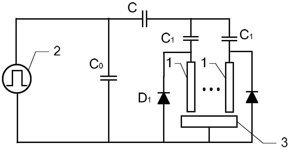
[0034] Specific implementation mode two: see image 3 This embodiment is described. The difference between this embodiment and the new EDM circuit that can realize multi-point discharge and high-speed EDM described in the first embodiment is that it also includes N diodes D 1 , the N diodes D 1 The cathodes are respectively connected with N isolation capacitors C 1 One end of the connection, N diodes D 1 The anode of the same time with the compensation capacitor C 0 The other end is connected to the negative pole of the pulse power supply 2.
[0035] In this embodiment, the positive polarity processing is realized by connecting diodes in parallel;
[0036] When the value of N is 2, in this embodiment, the discharge waveform of electrode 1 has a duty cycle of 80%. For details, see Figure 6 ,From Figure 6 It can be seen from the figure that the electrode 1 can realize negative polarity discharge, therefore, a new type of EDM circuit that can realize multi-point discharge...
specific Embodiment approach 3
[0037] Specific implementation mode three: see Figure 4 This embodiment is described. The difference between this embodiment and the new EDM circuit that can realize multi-point discharge and high-speed EDM described in the first embodiment is that it also includes N diodes D 1 , the N diodes D 1 The anodes are respectively connected to N isolation capacitors C 1 One end of the connection, N diodes D 1 The cathode simultaneously with the compensation capacitor C 0 The other end is connected to the negative pole of the pulse power supply 2.
[0038] In this embodiment, the positive polarity processing is realized by connecting diodes in parallel;
[0039] When the value of N is 2, in this embodiment, the discharge waveform of electrode 1 has a duty cycle of 50%. For details, see Figure 7 ,From Figure 7 It can be seen from the figure that the electrode 1 can realize positive polarity discharge. Therefore, a new type of EDM circuit that can realize multi-point discharge ...
PUM
 Abstract
Description
Claims
Application Information
 - R&D
- Intellectual Property
- Life Sciences
- Materials
- Tech Scout
- Unparalleled Data Quality
- Higher Quality Content
- 60% Fewer Hallucinations
Browse by: Latest US Patents, China's latest patents, Technical Efficacy Thesaurus, Application Domain, Technology Topic, Popular Technical Reports.
© 2025 PatSnap. All rights reserved.Legal|Privacy policy|Modern Slavery Act Transparency Statement|Sitemap|About US| Contact US: help@patsnap.com


