Planar helical antenna of combined structure

A plane spiral, composite structure technology, applied in the direction of the antenna, resonant antenna, mid-position feed between antenna terminals, etc., can solve the problems of general antenna effect and poor circular polarization performance of antenna performance, and achieve circular polarization performance. Increase, reduce antenna size, increase the effect of gain

Inactive Publication Date: 2014-09-03
JIANGSU UNIV OF SCI & TECH
View PDF2 Cites 15 Cited by
  • Summary
  • Abstract
  • Description
  • Claims
  • Application Information

AI Technical Summary

Problems solved by technology

However, there are still problems with the above two improvement methods. One is that the effect of reducing the size of the antenna is general, and the other is that the performance of the antenna, especially the circular polarization perfo

Method used


Image

  • Planar helical antenna of combined structure
  • Planar helical antenna of combined structure
  • Planar helical antenna of combined structure

Examples


Embodiment Construction

[0018] The present invention will be further described below in conjunction with the accompanying drawings and specific embodiments.

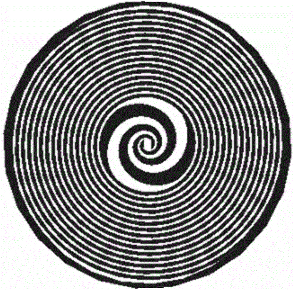
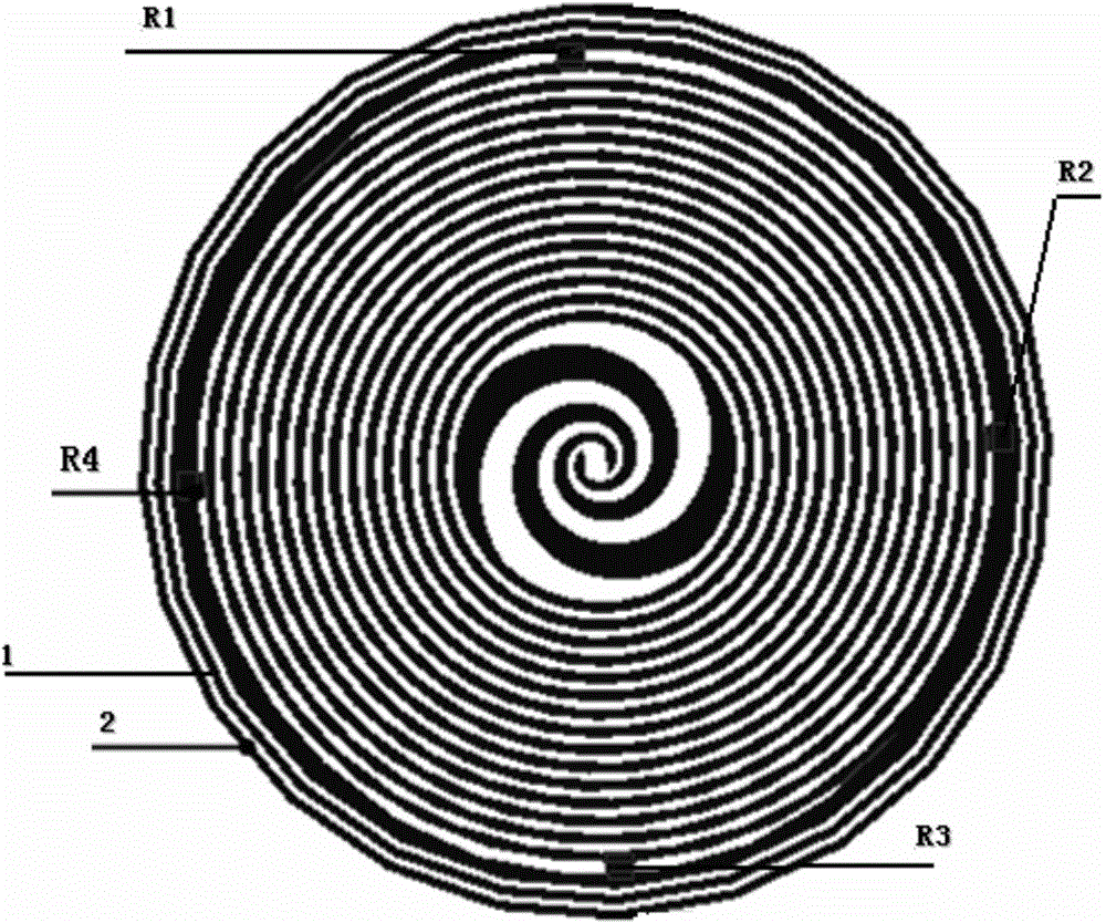
[0019] Such as figure 1 As shown, the composite structure planar helical antenna of the present invention includes a base plate part and an antenna part, and the antenna part is covered on the base plate part, and is a slot radiation planar helical antenna, including antenna arms and slot slits, and the antenna arms are double-arm symmetrical structure. The gap part of the slot is a combination of the equiangular helical antenna and the Archimedes helical antenna. The inner ring adopts an equiangular helical structure. The initial radius of the equiangular helix is ​​r=1mm, and the spiral growth rate is 0.221. A total of one and a half circles, the corresponding angle range is 0 to 2*π*1.5. The outer ring adopts the Archimedes spiral structure, the initial radius is set to 2.79mm, and the spiral growth rate is 0.12. The corresponding angle ra...


PUM

PropertyMeasurementUnit
Radiusaaaaaaaaaa
Diameteraaaaaaaaaa
Resistance valueaaaaaaaaaa

Abstract

The invention discloses a planar helical antenna of a combined structure. A planar equiangular helical antenna is combined with a planar Archimedes screw antenna. One and half ring of equiangular helix structure is used in the inner ring, an Archimedes helix structure is used in the outer ring, and the tail end of equiangular helix is in seamless connection with the initial end of Archimedes helix. The planar helical antenna of the combined structure is a groove-radiation planar helix antenna with double symmetrical arms, the diameter of the antenna is 50mm, the thickness of an antenna base plate is 0.8mm, and a dielectric slab of a dielectric constant of 2.2 is used. The planar helical antenna also comprises four surface-mounted resistors, wherein the resistance of the resistor is 160ohm, the resistors are connected between the outermost ring and the last but one ring of the antenna, and the angle between the adjacent surface-mounted resistors is 90degree; and the antenna further comprises two copper rings arranged in the periphery of the antenna. According to the invention, the size of the planar helical antenna is effectively reduced, and the circular polarization performance of the antenna is improved.

Description

technical field [0001] The invention relates to a planar helical antenna, in particular to a miniaturized composite structure planar helical antenna, which belongs to the technical field of microwave antennas. Background technique [0002] The concept of ultra-wideband antenna was proposed by Ramsey in 1957. Ultra-wideband refers to the relative bandwidth of antenna sending and receiving signals. When the ratio of signal bandwidth to center frequency is less than 1%, it is called narrowband. Bandwidth and center frequency The ratio between 1% and 25% is called broadband, and when the ratio of bandwidth to center frequency is greater than 25%, it is called ultra-wideband. An ultra-wideband antenna is an antenna device used to transmit and receive ultra-wideband signals. UWB antennas in the prior art include equiangular planar helical antennas and Archimedes planar helical antennas developed by Dyson et al. [0003] However, the development of planar helical antennas has bee...

Claims


Application Information

Patent Timeline
IPC IPC(8): H01Q9/27H01Q23/00
Inventor 田雨波刘东王兆尹
Owner JIANGSU UNIV OF SCI & TECH
Why Eureka
Try Eureka