Small self-propelled total-mixed-ration fodder mixing machine
A kind of mixing machinery and self-propelled technology, which is applied in the field of animal husbandry feed processing equipment, can solve the problems of high price, unusable large-scale whole ration feed mixer, and huge TMR mixer, so as to reduce friction loss and improve universal joint The effect of transmission efficiency and compact structure
- Summary
- Abstract
- Description
- Claims
- Application Information
AI Technical Summary
Problems solved by technology
Method used
Image
Examples
Embodiment 1
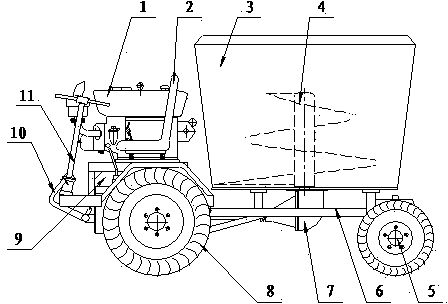
[0024] Such as figure 1 As shown, a small self-propelled full-ration feed mixing machine includes a large frame 6, a power mechanism, a stirring mechanism, a clutch brake mechanism, a walking mechanism, a seat 2, and an engine 1 and a gearbox 9 in the power mechanism. Wherein one side drive wheel direction of frame 6 deviates.
[0025] The present invention makes the layout of the gearbox asymmetrical due to the offset of the center of the gearbox 9 to one side. This structure makes full use of the existing mature gearbox technology. After the center is shifted, the diesel engine 1 is installed on the shifted side of the gearbox on the car body, and the operating mechanism and seat 2 are installed on the other side, making full use of the space, and the car body is compact and short. , which saves the cost and facilitates activities in the small space of the farm.
Embodiment 2
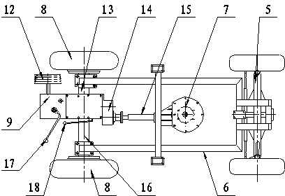
[0027] Running mechanism comprises the driving wheel assembly 8 that is positioned at big frame 6 front axle both sides and is positioned at the rear steering bridge assembly 5 of big frame 6 rear axles, and rear steering bridge assembly 5 is movably connected with big frame 6 rear parts with pin shaft. See figure 2 .
[0028] One side of the gearbox 9 is connected to the drive wheel on one side of the drive wheel assembly 8 through the short axis pipe 13, and the other side of the gearbox 9 is connected to the drive wheel on the other side of the drive wheel assembly 8 through the long axis pipe 16. Drive connection.
Embodiment 3
[0030] Power mechanism also comprises reduction box 14, and reduction box 14 is installed in the rear portion of gearbox 9, is used for decelerating and simultaneously adjusts the PTO shaft of reduction box 14 to the intermediate position of frame, makes the PTO shaft of reduction box 14 and stirring mechanism The center of the power input shaft of the reversing reduction mechanism assembly 7 at the bottom is up and down, left and right straight on a line.
[0031] The power output shaft of the reduction box 14 is connected with the power input shaft of the reverse reduction mechanism assembly 7 through a universal joint transmission shaft 15 .
[0032] The gearbox 9 is also provided with a rear power output handle 18 that is used to cut off or connect the power delivered to the reduction box 14. By manipulating the rear power output handle 18, the stirring mechanism is powered and runs to complete the stirring operation of the forage grass.
[0033] In this embodiment, the ge...
PUM
 Abstract
Description
Claims
Application Information
 - R&D
- Intellectual Property
- Life Sciences
- Materials
- Tech Scout
- Unparalleled Data Quality
- Higher Quality Content
- 60% Fewer Hallucinations
Browse by: Latest US Patents, China's latest patents, Technical Efficacy Thesaurus, Application Domain, Technology Topic, Popular Technical Reports.
© 2025 PatSnap. All rights reserved.Legal|Privacy policy|Modern Slavery Act Transparency Statement|Sitemap|About US| Contact US: help@patsnap.com


