

Pitch mixed material warm-mixing and regenerating equipment
A technology of asphalt mixture and recycling equipment, which is applied in the direction of climate change adaptation, roads, road repairs, etc. It can solve the problems of low energy consumption and exhaust emissions, low mixing and compaction temperature, excessive aging of asphalt, etc., to reduce fuel consumption , solve the effect of bonding and reducing pollution
- Summary
- Abstract
- Description
- Claims
- Application Information
AI Technical Summary
Problems solved by technology
Method used
Image

Examples
Embodiment Construction
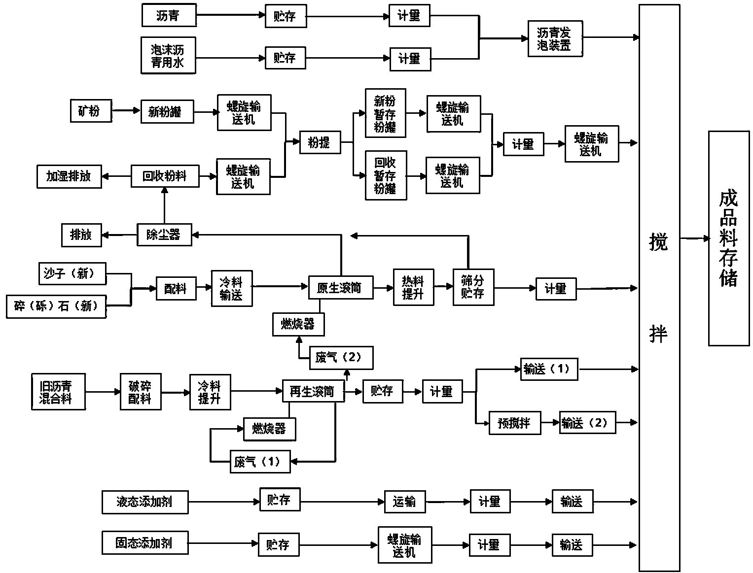
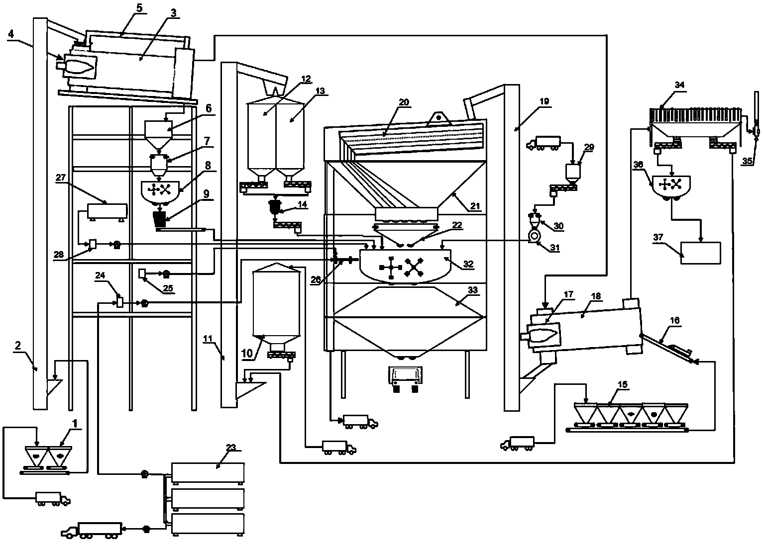
[0017] Such as figure 1 , figure 2 The asphalt mixture warm-mix regeneration equipment shown includes: including asphalt mixture plant-mixed primary system, asphalt mixture plant-mixed regeneration system, additive treatment system and tail gas treatment system, asphalt spraying in asphalt mixture plant-mixed primary system The system is a warm-mix foam asphalt spraying system, which adds foam asphalt to the new aggregate prepared by the original asphalt mixing system in the asphalt mixture plant and the regenerated hot material prepared by the asphalt mixture regeneration system in the mixing tank, together with the asphalt mixed in the mixing tank The liquid and solid additives are stirred to prepare the finished asphalt mixture.
[0018] The original asphalt mixing plant system is composed of a new aggregate grading device 15, a large-size aggregate vibrating screen 16, a burner 17, a drying drum 18, and a hot aggregate hoist in sequence according to the new aggregate pro...
PUM
 Abstract
Description
Claims
Application Information