
Multi-gas mixed combustion boiler and combustion method

A technology of gas mixing and gas, which is applied in the field of boilers and boiler combustion, can solve the problems of incombustible gas, waste of resources, singleness, etc., and achieve the effects of optimizing the configuration of energy structure, saving energy, and shortening the residence time

Inactive Publication Date: 2014-09-10
JIGANG GRP
View PDF9 Cites 5 Cited by
  • Summary
  • Abstract
  • Description
  • Claims
  • Application Information

AI Technical Summary

Problems solved by technology

[0002] Traditional gas-fired boilers are single or mixed with another gas in a certain proportion in the main combustion gas, and the combustion calorific value is stable, and the gas mixed with different gases cannot be burned.
There are three kinds of by-product gas produced in the production of iron and steel enterprises: coke oven gas, blast furnace gas and converter gas. The three kinds of gas have different calorific values. The calorific value of coke oven gas is the highest, followed by converter gas and blast furnace gas. The lowest, and the combustion gas used by boilers is usually the above situation, and it is not possible to burn multiple gases (coke oven gas, converter gas and blast furnace gas) at the same time. When the three kinds of gas are surplus, the gas must be released, resulting in waste of resources
[0003] Currently, there is no good solution

Method used


Image

  • Multi-gas mixed combustion boiler and combustion method
  • Multi-gas mixed combustion boiler and combustion method

Examples


Embodiment Construction

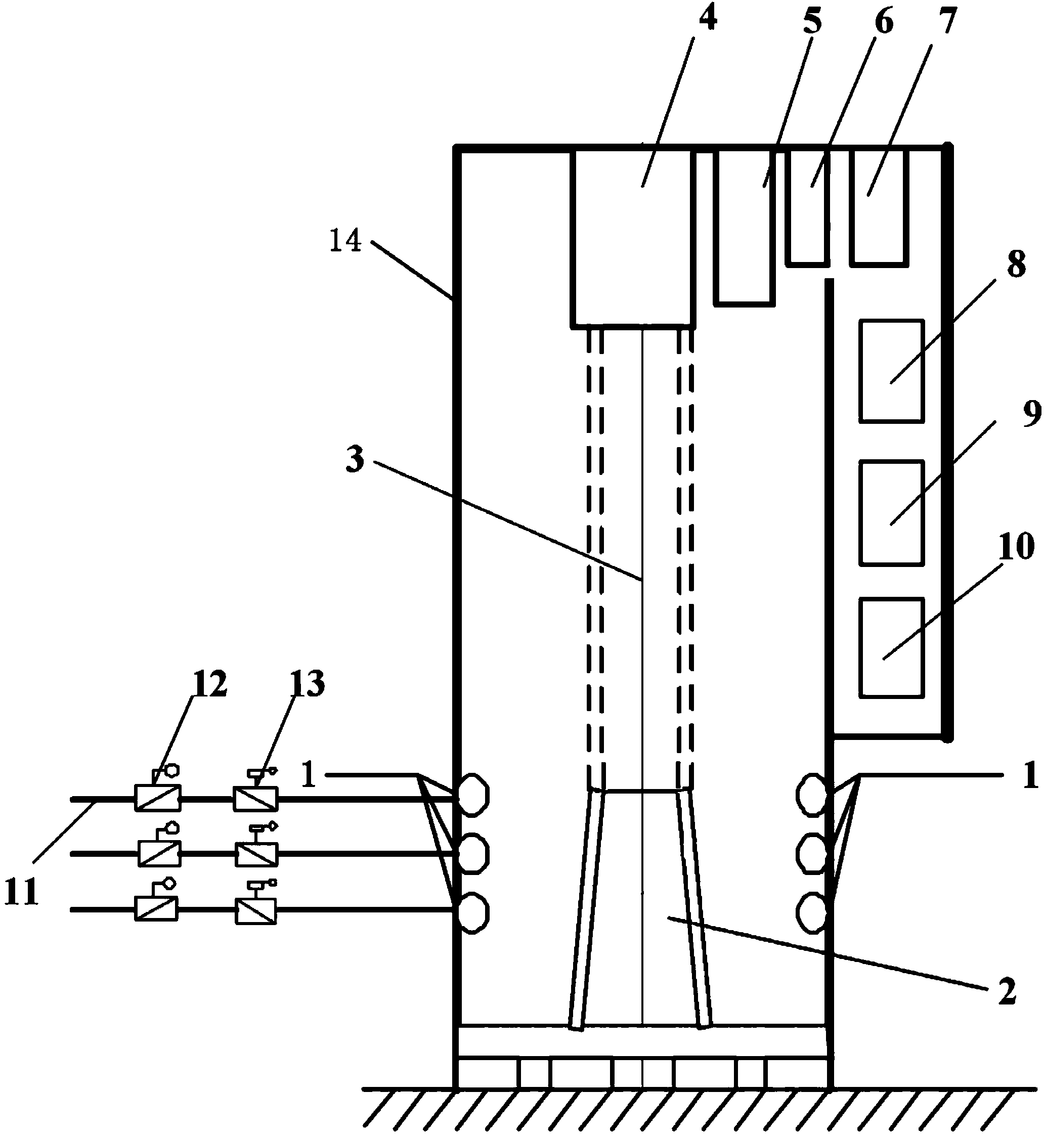
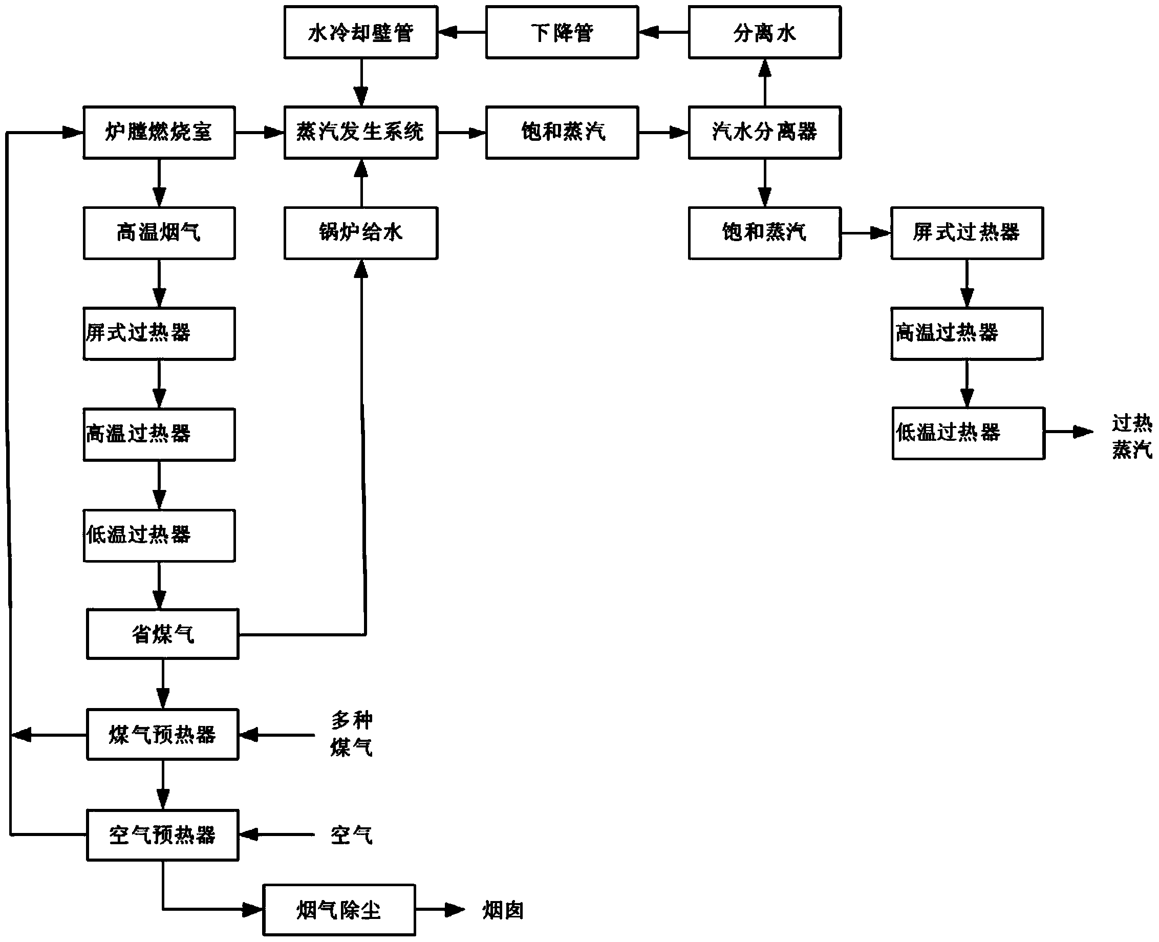
[0014] Refer to the attached figure 1 And attached figure 2 Various gas mixed combustion boilers and combustion methods of the present invention will be described in detail below.

[0015] Various gas mixed combustion boilers, its structure includes furnace 3, furnace water wall 14, steam generation system 4, panel superheater 5, high temperature superheater 6, low temperature superheater 7, economizer 9, air preheater 9 and The gas preheater 10, the furnace water-cooled wall 14 is arranged on the outside of the furnace 3, the top of the furnace 3 is provided with a steam generating system 4, the flue on the right side of the furnace 3 is provided with a panel superheater 5, The high-temperature superheater 6 and the low-temperature superheater 7 are provided with an economizer 8, an air preheater 9 and a gas preheater 10 in the flue at the lower part of the low-temperature superheater 7, and a gas combustion stabilizer is provided at the lower part of the furnace 3 2. The ...


PUM


Abstract

The invention discloses a multi-gas mixed combustion boiler and a combustion method, and belongs to boilers and combustion methods. The multi-gas mixed combustion boiler structurally comprises a hearth, a hearth water cooling wall, a steam generating system, a platen superheater, a high-temperature superheater, a low-temperature superheater, a coal economizer, an air preheater and a gas preheater. A gas combustion stabilizer is arranged on the lower portion of the hearth, three layers of gas combustors are arranged on the outer side of the gas combustion stabilizer, and the outer sides of the three layers of gas combustors are respectively connected with three gas pipelines. The combustion method includes enabling various gases and air to proportionally flow into the hearth to be combusted; transmitting heat to the steam generating system; enabling saturated steam to flow through the superheaters and then heating the saturated steam to obtain superheated steam; enabling flue gas to flow through the superheaters; then preheating water by the aid of the coal economizer, and heating the flue gas by the air preheater and the coal preheater; finally exhausting the flue gas into the atmosphere. The flue gas is generated after fuel is combusted. The water is about to be fed to the boiler. The multi-gas mixed combustion boiler and the combustion method have the advantages that coke-oven gas, blast-furnace gas and converter gas can be combusted by the aid of the multi-gas mixed combustion boiler and the combustion method; a large quantity of energy can be saved, severe environmental pollution due to gas emission can be prevented, the production cost can be reduced, and the like.

Description

technical field [0001] The invention relates to a boiler and a boiler combustion method, in particular to a multi-gas mixed combustion boiler and a combustion method. Background technique [0002] Traditional gas-fired boilers are single or mixed with another gas in a certain proportion in the main combustion gas, and the combustion calorific value is stable, and the gas mixed with different gases cannot be burned. There are three kinds of by-product gas produced in the production of iron and steel enterprises: coke oven gas, blast furnace gas and converter gas. The three kinds of gas have different calorific values. The calorific value of coke oven gas is the highest, followed by converter gas and blast furnace gas. The lowest, and the combustion gas used by boilers is usually the above-mentioned situation, and it is not possible to burn multiple gases (coke oven gas, converter gas and blast furnace gas) at the same time. When the three kinds of gas are surplus, the gas mus...

Claims


Application Information

Patent Timeline
IPC IPC(8): F22B31/00F23C5/08
Inventor 王文涛战玉生马庆涛
Owner JIGANG GRP
Learn More