Apparatus for high gravity removal of hydrogen sulfide of novel industrial gas, and technology thereof

A technology for industrial gas and hydrogen sulfide, which is used in the preparation/purification of sulfur, chemical instruments and methods, separation methods, etc., can solve problems such as complex processes, and achieve the effects of simplifying the process flow, enhancing mass transfer efficiency, and reducing equipment size

Active Publication Date: 2014-09-17
BEIJING UNIV OF CHEM TECH +2
View PDF13 Cites 19 Cited by
  • Summary
  • Abstract
  • Description
  • Claims
  • Application Information

AI Technical Summary

Problems solved by technology

[0012] The second technical problem to be solved by the present invention is to provide a new type of process for removing hydrogen sulfide from industrial gas by supergravity; the process uses the above-mentioned device, which simplifies the complex

Method used


Image

  • Apparatus for high gravity removal of hydrogen sulfide of novel industrial gas, and technology thereof
  • Apparatus for high gravity removal of hydrogen sulfide of novel industrial gas, and technology thereof

Examples


Embodiment 1

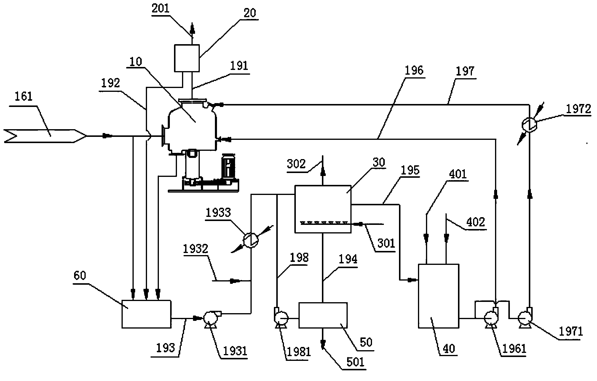
[0044] A new type of device for removing hydrogen sulfide from industrial gases by supergravity, including a supergravity machine 10, a gas-liquid separation device 20, an oxidation tank 30, a lean liquid tank 40, a drum vacuum filter 50 and a rich liquid tank 60;

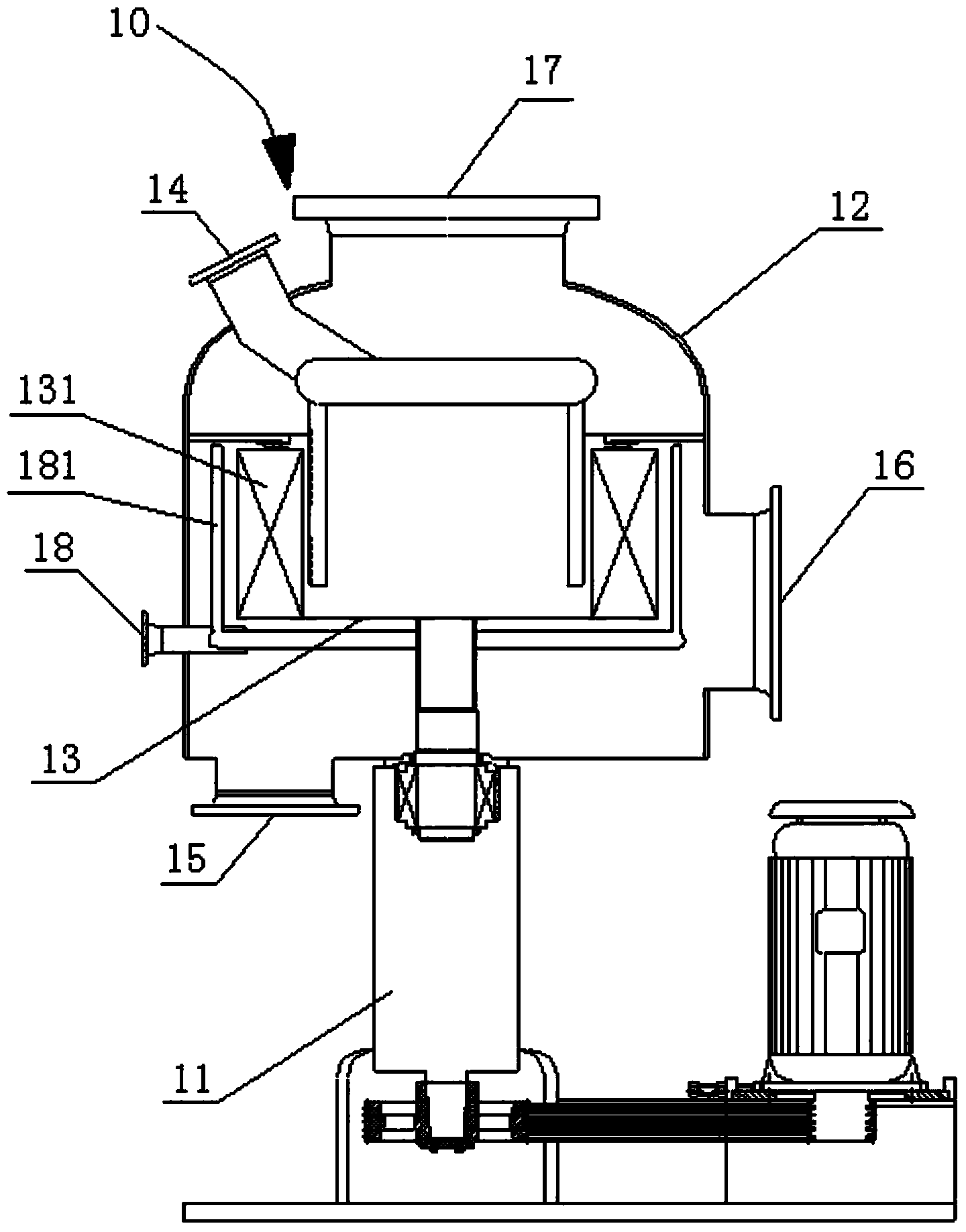
[0045] The supergravity machine 10 comprises a power unit 11, a housing 12, a rotor 13, a liquid inlet 14, a liquid outlet 15, a gas inlet 16, a gas outlet 17 and a flushing liquid inlet 18; the power unit 11 is a motor, and the motor finally The output shaft of the transmission extends into the housing 12 and is fixedly connected with the rotor 13. The upper end of the housing 12 is provided with a liquid inlet 14 and a gas phase outlet 16, and the lower end of the housing 12 is provided with a liquid outlet 15 and a gas inlet 16; the rotor 13 is provided with a packing 131, and the outer layer of the rotor packing 131 is provided with a backwashing device 181, and the backwashing device 181 is connected to the flu...

Embodiment 2

[0068] Use the device and technology of embodiment 1 to carry out oilfield associated gas removal hydrogen sulfide:

[0069] Capacity: 10000Nm 3 / d, pressure 10MPa, hydrogen sulfide content 100ppm, gas temperature 50℃, complex iron as absorbent, absorption liquid consumption 100m 3 / h. After being treated by this process, the associated gas H is exported 2 The S content is less than 3ppm.

Embodiment 3

[0071] Use the device and technique of embodiment 1 to carry out the removal of hydrogen sulfide from natural gas:

[0072] Capacity: 50000Nm 3 / d, pressure 0.9MPa, hydrogen sulfide content 5000ppm, gas temperature 5℃, complex iron as absorbent, absorption liquid consumption 100m 3 / h. After being treated by this process, the exported natural gas H 2 The S content is less than 10 ppm.


PUM


Abstract

The invention discloses an apparatus for the high gravity removal of hydrogen sulfide of a novel industrial gas. The apparatus comprises a high gravity machine, a gas-liquid separation device, an oxidation tank, a lean liquid tank, a rotary drum vacuum filter and a rich liquid tank; the high gravity machine comprises a power device, a shell, a rotor, a liquid inlet, a liquid outlet, a gas inlet, a gas outlet and a flushing liquor inlet; the output shaft of the power device stretches into the shell and is fixedly connected with the rotor, the upper end surface of the shell is provided with the liquid inlet and the gas outlet, and the lower end of the shell is provided with the liquid outlet and the gas inlet; and the rotor is provided with a filler, the external layer of the rotor filler is provided with a backwashing device, and the backwashing device is connected with the flushing liquor inlet. The adoption of a backwashing high-gravity rotary filler bed greatly prevents the obstruction of the high gravity filler by sulfur particles. The adoption of the drum air regeneration oxidation tank substantially simplifies the process flow and substantially reduces the cost. The apparatus and the method can be used for the desulphurization of high concentration hydrogen sulfide gases in order to prevent the obstruction of the rotor filler by sulfur.

Description

technical field [0001] The technology of the present invention relates to a device and a process for removing hydrogen sulfide, in particular to a device and a process for removing hydrogen sulfide from a new type of industrial gas by supergravity. technical background [0002] Gases containing hydrogen sulfide are very common in industry, such as natural gas, oilfield associated gas, semi-water gas, coke oven gas, synthesis gas, etc. Hydrogen sulfide gas will seriously corrode metal pipes, damage equipment and measuring instruments under aerobic or humid heat conditions. If hydrogen sulfide gas is directly discharged, it will cause adverse effects on production operations, the surrounding environment and factory workers, and is one of the environmental pollutants that must be eliminated or controlled. [0003] The selection of various purification methods should be based on the nature and source of the exhaust gas. For waste gas from chemical industry and light industry, ...

Claims


Application Information

Patent Timeline
IPC IPC(8): B01D53/78B01D53/52B01D53/96C01B17/05
Inventor 陈建峰梁作中赵宏孙宝昌初文广邹海魁罗勇
Owner BEIJING UNIV OF CHEM TECH
Why Eureka
Try Eureka