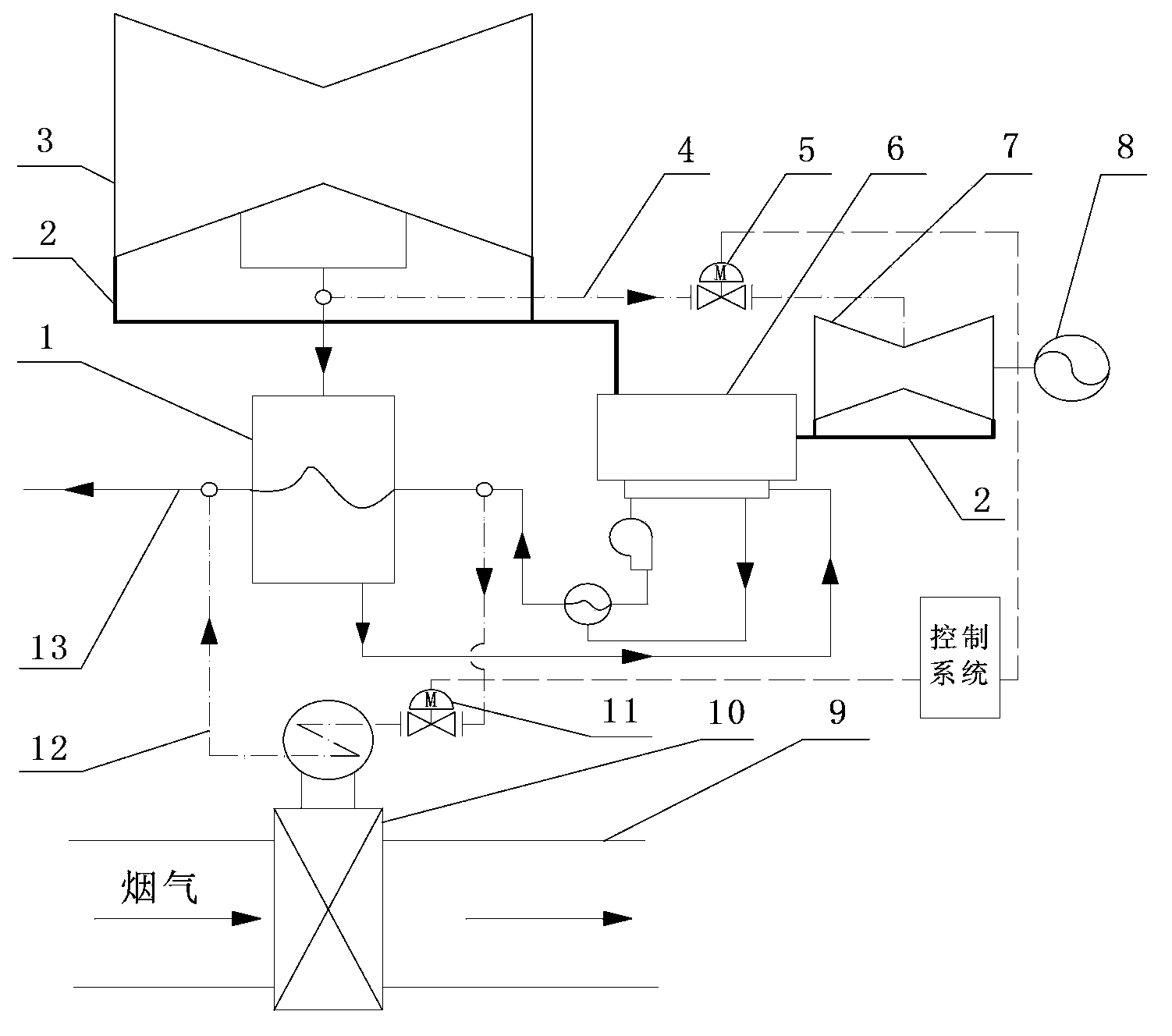
System utilizing smoke low-temperature residual heat of generator unit to generate power

A technology for low-temperature waste heat and generator sets, which is applied to machines/engines, preheating, waste heat treatment, etc., and can solve problems such as low power generation efficiency, low steam grade, and low waste heat grade, achieving remarkable energy-saving effects, high power generation efficiency, and reduced effect of influence

Active Publication Date: 2014-09-17
SHANGHAI FUBO ENVIRONMENTAL PROTECTION EQUIP
View PDF10 Cites 3 Cited by
  • Summary
  • Abstract
  • Description
  • Claims
  • Application Information

AI Technical Summary

Problems solved by technology

Due to the low exhaust gas temperature of the boiler, the grade of waste heat recovered by general waste heat recovery technology is low. In large-scale generating units, there is no suitable and effective utilization method. As a result, waste heat recovery projects cannot be used on large-scale generating units. This is also One of the main problems encountered in the low temperature waste heat energy saving of large generating units at present
Moreover, on large-scale generator sets, low-grade heat energy is relatively abundant. Therefore, can a large amount of low-grade heat energy be utilized through some technical solutions, and quantitative changes can cause qualitative changes, so that some higher-grade heat energy can be obtained. of heat energy, and effectively utilize this part of high-grade heat energy? This

Method used


Image

  • System utilizing smoke low-temperature residual heat of generator unit to generate power

Examples


Embodiment Construction

[0028] The implementation of the present invention will be illustrated by specific specific examples below, and those skilled in the art can easily understand other advantages and effects of the present invention from the contents disclosed in this specification.

[0029] see figure 1 . It should be noted that the structures, proportions, sizes, etc. shown in the drawings attached to this specification are only used to match the content disclosed in the specification, for those who are familiar with this technology to understand and read, and are not used to limit the implementation of the present invention. Limiting conditions, so there is no technical substantive meaning, any modification of structure, change of proportional relationship or adjustment of size, without affecting the effect and purpose of the present invention, should still fall within the scope of the present invention. The disclosed technical content must be within the scope covered. At the same time, term...


PUM


Abstract

The invention provides a system utilizing low-temperature smoke residual heat of a generator unit to generate power. The system comprises a first steam power generation system, a condensing water pipeline, a low pressure heater and a steam condenser, wherein the low pressure heater and the steam condenser are arranged on the condensing water pipeline, the first steam power generation system comprises a low pressure cylinder, a smoke residual heat recycling device and a second steam power generation system, the low pressure heater is connected with the low pressure cylinder, the smoke residual heat recycling device comprises a heat absorbing section and a heat releasing section, the heat absorbing section is arranged in a boiler flue, the heat releasing section is arranged on a condensing water branch pipe which is parallelly connected with the condensing water pipeline, the second steam power generation system comprises a second steam turbine and a second generator which are connected, the second steam turbine is connected with the low pressure cylinder through a steam suction pipe, and the low pressure cylinder and the second steam turbine are connected with the condenser through steam exhaust pipes. The system has the advantages that the low-temperature smoke residual heat can be safely recovered, the recovered residual heat is used for generating power again by the cascade utilization method, the traditional problem of inaccurate metering of the power generation by recovered residual heat is solved, the problem of low-efficiency utilization of low-temperature residual heat of large power plants is also solved, and the power plant can reach the energy-saving and environment-protection purposes.

Description

technical field [0001] The invention relates to the technical field of thermal power generation, in particular to a system for generating electricity by utilizing the low-temperature waste heat of flue gas from a generator set. Background technique [0002] Under the situation that the country vigorously advocates energy conservation and environmental protection and enterprises are developing themselves, the efficiency of boilers is getting higher and higher. Smoke temperature is one of the important indicators to measure boiler efficiency. The higher the exhaust gas temperature, the greater the exhaust gas loss and the lower the boiler efficiency. Therefore, the current exhaust gas temperature of boilers is lower. Now the exhaust gas temperature of large and medium-sized boilers is generally around 135 ° C, especially for large boilers. The air preheater is generally a rotary air preheater, so its exhaust gas temperature may be lower. [0003] Although the exhaust gas tem...

Claims


Application Information

Patent Timeline
IPC IPC(8): F01K7/34F01K11/02F22D1/00F27D17/00
CPCY02P80/15
Inventor 钱学略屈鹏飞
Owner SHANGHAI FUBO ENVIRONMENTAL PROTECTION EQUIP
Why Eureka
Try Eureka