
An electron beam accelerating power supply device and control method

A technology of power supply control and electron beam, which is applied in the direction of control/regulation system, output power conversion device, electrical components, etc. It can solve the problem of ineffective filtering of inductance, reduced ability to eliminate peak and sag voltage, and small capacitance value of high-voltage capacitors. And other issues

Active Publication Date: 2017-05-03
GUILIN UNIV OF ELECTRONIC TECH
View PDF3 Cites 0 Cited by
  • Summary
  • Abstract
  • Description
  • Claims
  • Application Information

AI Technical Summary

Problems solved by technology

Due to the presence of parasitic parameters of high-voltage filter inductors and capacitors, the ability to eliminate peak and sag voltages is greatly reduced
In addition, the working current of the high-voltage power supply is generally small, the inductance has little effect on filtering the normal ripple, and the capacitance value of the high-voltage capacitor is small. All these factors are not conducive to reducing the ripple of the output voltage.

Method used


Image

  • An electron beam accelerating power supply device and control method
  • An electron beam accelerating power supply device and control method
  • An electron beam accelerating power supply device and control method

Examples


Embodiment Construction

[0064] The principles and features of the present invention are described below in conjunction with the accompanying drawings, and the examples given are only used to explain the present invention, and are not intended to limit the scope of the present invention.

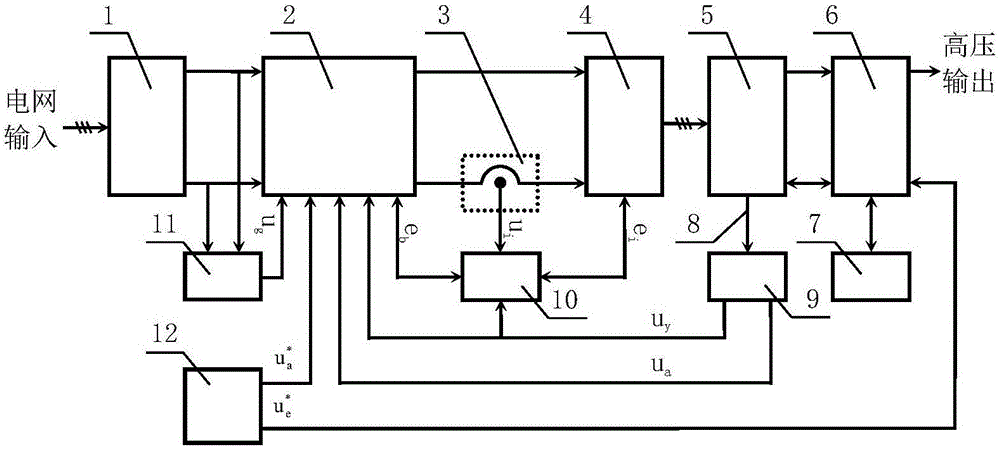
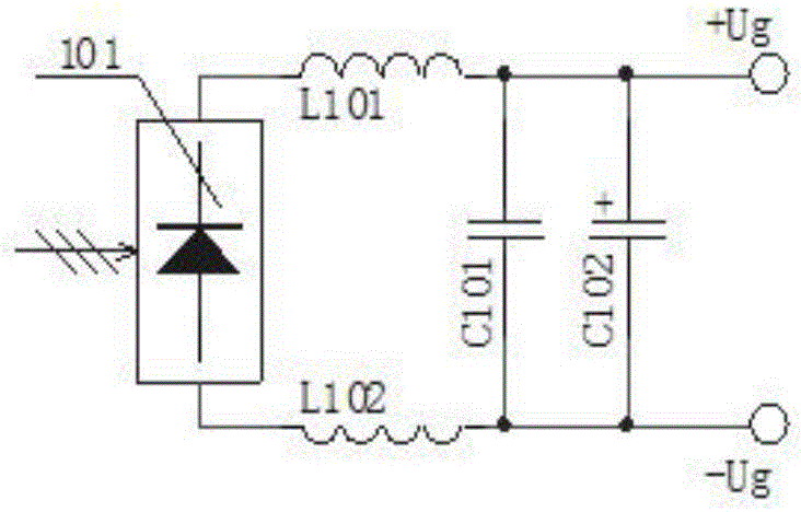
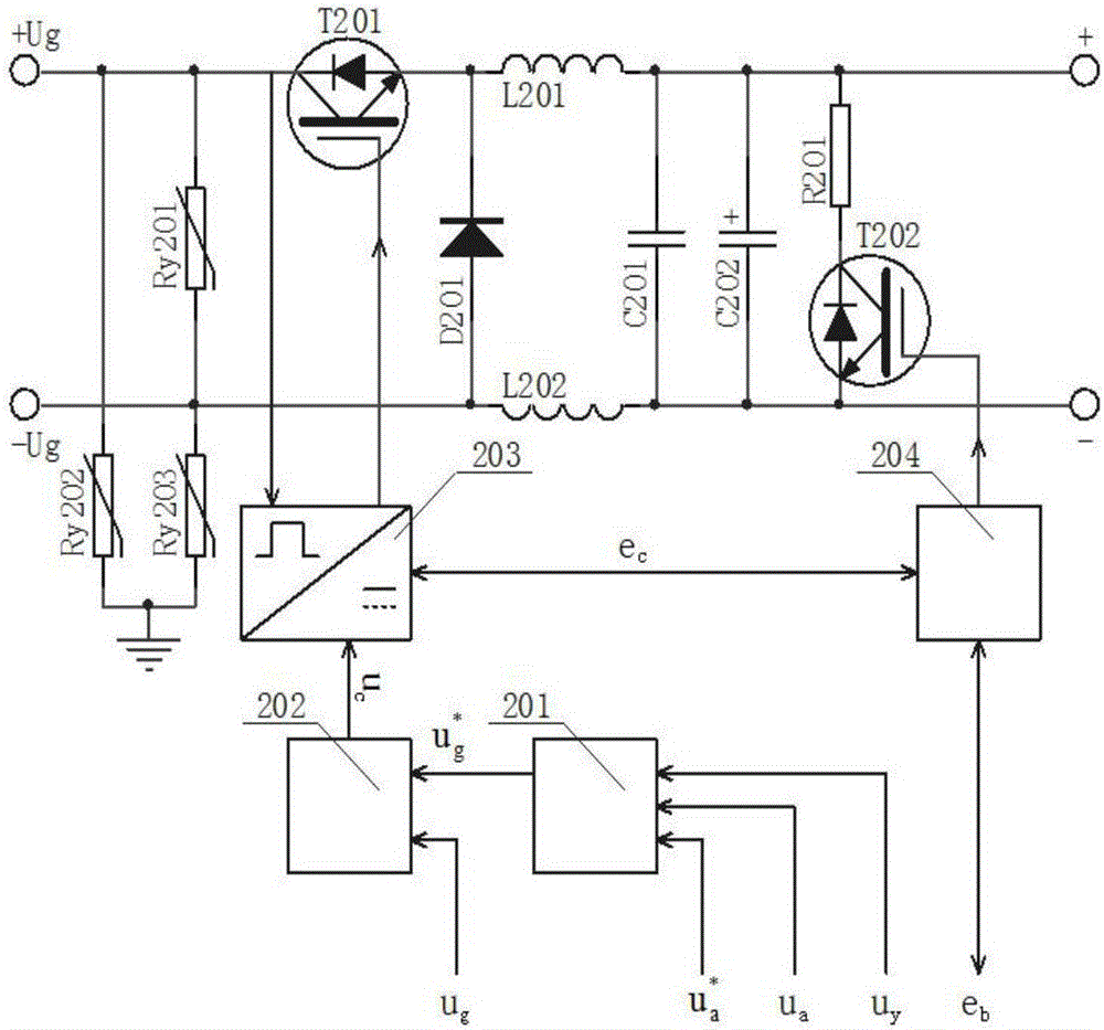
[0065] Such as figure 1 As shown, an electron beam accelerated power supply control method adopts a double closed-loop voltage stabilization control method. The pre-stage voltage stabilization system uses a DC-DC converter 2 for voltage regulation, a three-phase rectangular wave inverter for 4 inverters, and a multi-phase rectangular wave inverter. Wave high-voltage AC rectification and filtering, parallel voltage stabilization at the output of high-voltage stabilizing components, comprehensive feedback of sampling signals for outputting high-voltage and stabilizing component currents, and low-voltage power supply DC feed-forward compensation to suppress ripples. , Negative feedback control of output voltage samplin...


PUM


Abstract

The invention relates to an electron beam acceleration power device and a control method. The double-closed-loop voltage stabilizing control method is adopted, according to a front-stage voltage stabilization system, a DC-DC converter is used for voltage regulation, a three-phase rectangular wave inverter is used for inversion, a multi-phase rectangular wave high-voltage alternating current rectifier is used for filtering, high-voltage voltage stabilization element output ends are connected in parallel for voltage stabilization, sampling signals of high voltage element currents and sampling signals of voltage stabilization element currents are output for comprehensive feedback, and low-voltage power supply direct currents are fed forwards for compensation to retrain ripple waves. According to a rear-stage voltage stabilization system, high-voltage electron tubes are connected in series for regulation, voltage sampling signals are output for negative feedback control, a sampling element and a regulator are made to be constant in temperature to improve voltage stabilization precision and dynamic regulation speed. Compared with the prior art, high-voltage rectification conventional ripples, sag voltages and peak pulse voltages can be restrained, and the output voltage stabilization precision and dynamic regulation speed are improved.

Description

technical field [0001] The invention relates to the technical field of electron beam processing equipment, in particular to an electron beam accelerating power supply device and a control method. Background technique [0002] Electron beam processing equipment is more and more widely used, and electron beam precision processing equipment has higher and higher requirements for its acceleration power supply. On the one hand, it has higher requirements on the stability of the acceleration voltage. Smaller, such as the acceleration voltage of the electron gun acceleration power supply for the fourth-generation light source reaches 500kV, and the peak-to-peak value is less than 0.05%. For such a demanding requirement, the current conventional high-voltage power supply cannot meet it. The bottleneck lies in the peak-to-peak value of the ripple index. The DC high-voltage power supply is obtained by AC boosting and then rectification and filtering. The ripple is in addition to the r...

Claims


Application Information

Patent Timeline
Patent Type & Authority Patents(China)
IPC IPC(8): H02M1/14H02M3/156H02M1/32H02M7/5387
Inventor 韦寿祺李雪娇莫金海陈叙黎明崔九喜
Owner GUILIN UNIV OF ELECTRONIC TECH
Learn More