Optical element, optical thin film forming device, and optical thin film forming method
An optical thin film and film-forming technology, which is applied in the direction of optical components, optics, instruments, etc., can solve the problems of difficult film formation at the periphery and easy thinning of physical film thickness
Active Publication Date: 2017-10-17
HOYA CORP
View PDF1 Cites 0 Cited by
- Summary
- Abstract
- Description
- Claims
- Application Information
AI Technical Summary
Problems solved by technology
For example, when forming a film on the concave surface of a concave meniscus lens used as a camera lens, it is difficult to form a film on the peripheral part, and the physical film thickness tends to be thinner than that on the central part.
Therefore, it is easy to cause a difference in reflectance exceeding the allowable range due to the distribution of the optical film thickness between the center of the lens surface and its periphery.
Method used
View moreImage
Smart ImageViewing Examples
Examples
Embodiment 1
[0079] (Example 1) concave hemispherical lens, B270, 7 layers
Embodiment 2
[0080] (Example 2) concave hemispherical lens, B270, 7 layers
Embodiment 3
[0081] (Example 3) Concave aspheric lens, M-TAF101, 7 layers
Login to View More PUM
| Property | Measurement | Unit |
|---|---|---|
| Reflectivity | aaaaa | aaaaa |
Abstract
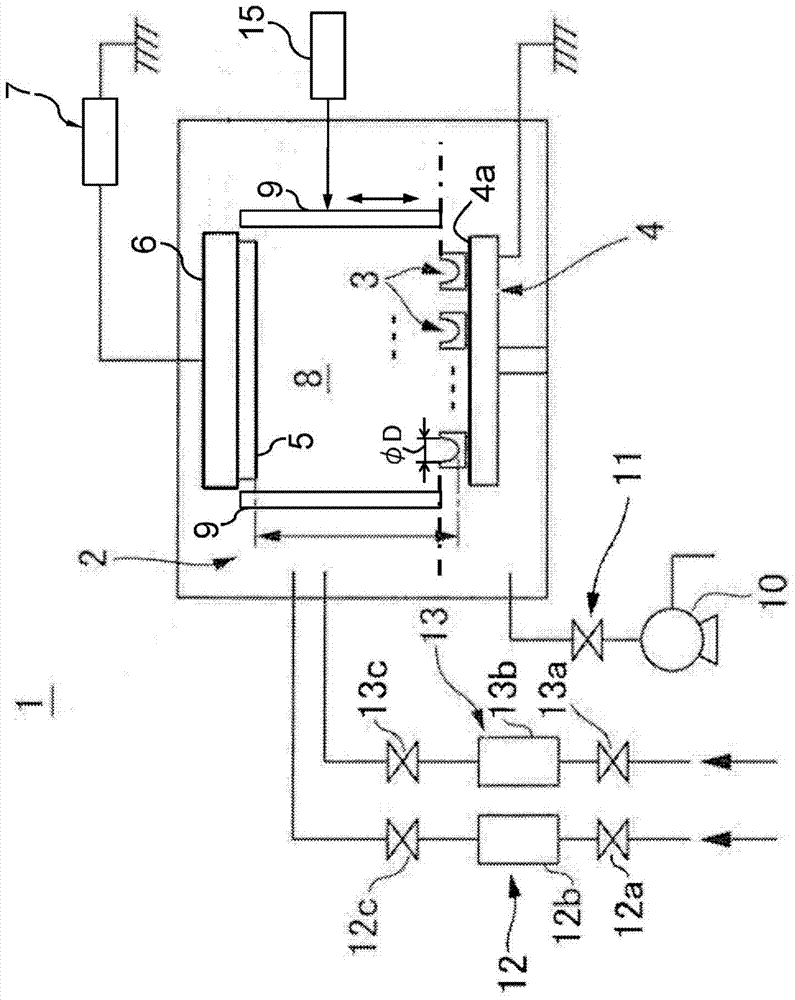
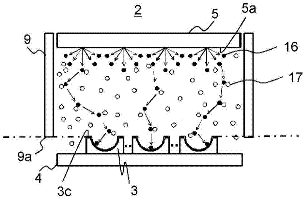
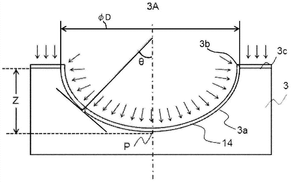
When forming an optical thin film (14) on the curved surface (3a) of the film-forming material (3), between the disposition part (4) and the target (5) as part of the space in the processing chamber (2) The specific space (8) is surrounded by the shielding part (9) in advance. In this state, an optical thin film having substantially the same optical film thickness is formed on the curved surface when film formation is performed by the following sputtering process in which an active gas and an inert gas are supplied in a vacuum state. A voltage is applied to the target (5) in the gas treatment chamber (2).
Description
technical field [0001] The present invention relates to an optical element in which an optical film is formed on a curved surface of a film-forming material such as a curved substrate or an optical lens, an optical thin film forming apparatus for forming the optical thin film thereof, and an optical thin film forming method. Background technique [0002] As a type of optical film, for example, an antireflection film is well known. In order to prevent the reduction of the loss of transmitted light and the occurrence of ghost flare, etc., on the surface of an imaging lens attached to a digital camera, etc., a projection lens attached to a liquid crystal projector, etc., or a cover glass of an optical device, etc. layer of anti-reflective coating. The antireflection film needs to be formed so that the desired antireflection characteristics can be obtained without causing a film thickness distribution of the optical film thickness. When forming an anti-reflection film on the l...
Claims
Login to View More Application Information
Patent Timeline
 IPC IPC(8): C23C14/34G02B1/11G02B3/02
CPCC23C14/34C23C14/04C23C14/08C23C14/10C23C28/04G02B1/115G02B3/04G02B1/11
Inventor 川岸秀一朗山下照夫
Owner HOYA CORP
Features
- R&D
- Intellectual Property
- Life Sciences
- Materials
- Tech Scout
- Unparalleled Data Quality
- Higher Quality Content
- 60% Fewer Hallucinations
Learn More Browse by: Latest US Patents, China's latest patents, Technical Efficacy Thesaurus, Application Domain, Technology Topic, Popular Technical Reports.
© 2025 PatSnap. All rights reserved.Legal|Privacy policy|Modern Slavery Act Transparency Statement|Sitemap|About US| Contact US: help@patsnap.com


