A device for preparing nanoporous film and its application

A nanoporous, control device technology, applied in the field of materials, to achieve the effect of a wide range of applications

Inactive Publication Date: 2017-06-30
能源X控股有限公司
View PDF10 Cites 0 Cited by
  • Summary
  • Abstract
  • Description
  • Claims
  • Application Information

AI Technical Summary

Problems solved by technology

[0004] How to prepare a large-area nanostructured film on the surface of the substrate, especially the nanoporous film technology that is different from the traditional dense film, there is no good method at home and abroad

Method used


Image

  • A device for preparing nanoporous film and its application
  • A device for preparing nanoporous film and its application
  • A device for preparing nanoporous film and its application

Examples


Embodiment 1

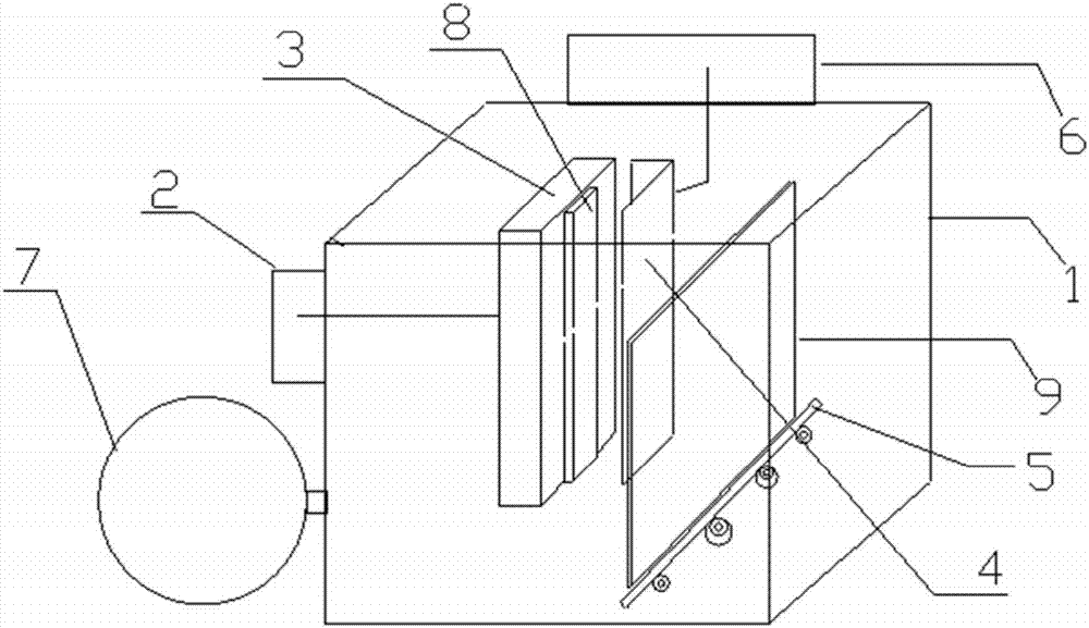
[0034] Devices for preparing nanoporous thin films, see figure 1 , including a deposition chamber (1), a voltage source (2), a shield support and control device (6), a vacuum pump (7), and a magnetron (3) and a shield ( 4), the substrate transport track (5); the voltage source (2) is connected to the magnetron (3); the sputtering target (8) is fixed on the magnetron (3). The substrate transport track (5) is used to carry the substrate through the deposition chamber (1).

[0035] The shield support and control device (6) is connected to the shield (4), and adopts common mechanical control technology to control and change the geometric shape, size and physical position of the shield (4) relative to the sputtering target during the deposition process. For example, the shielding screen (4) is controlled to move in parallel in front of the sputtering target (8); half of the deposited particle flow or one third of the particle flow is blocked. As another example, remove the shadow...

Embodiment 2

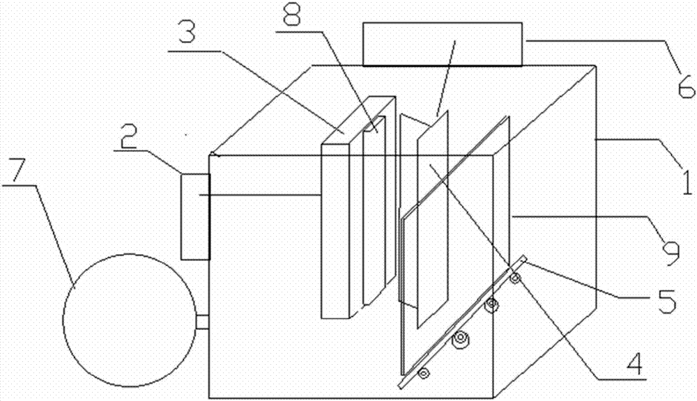
[0055] Devices for preparing nanoporous thin films, see image 3 , including a deposition chamber (1), a voltage source (2), a shield support and control device (6), a vacuum pump (7), and a magnetron (3) and a shield ( 4), the substrate transport track (5); the voltage source (2) is connected to the magnetron (3); the sputtering target (8) is fixed on the magnetron (3). The substrate transport track (5) is used to carry the substrate through the deposition chamber (1).

[0056] The shield support and control device (6) is connected to the shield (4), and adopts common mechanical control technology to control and change the geometric shape, size and physical position of the shield (4) relative to the sputtering target during the deposition process. For example, the shielding screen (4) is controlled to move in parallel in front of the sputtering target (8); half of the deposited particle flow or one third of the particle flow is blocked. As another example, remove the shadow...

Embodiment 3

[0065] The nanoporous structure film was prepared by using the device of Example 2, the method was basically the same as that of Example 1, the only difference was that a rotating target was used instead of a planar target.

[0066] Using this device to prepare nanoporous structure film, the method is the same as in Example 1. By controlling different process parameters, samples of nanoporous structure film with batch numbers 11-15 were prepared, and the porosity was between 0.10 and 0.80, as shown in Table 3.

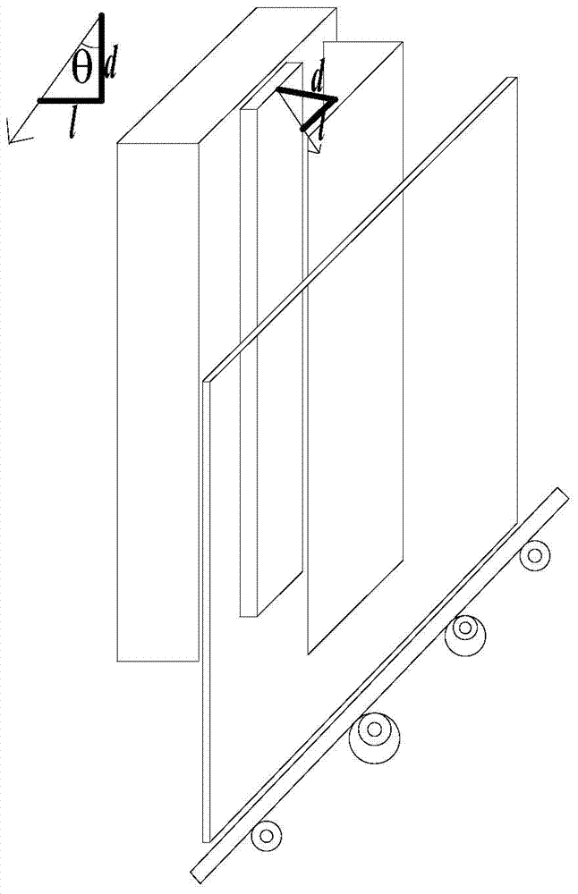
[0067] Five batches of samples of table 3 batch numbers 11-15 experimental conditions and performance measurement

[0068] Sample serial number 11 12 13 14 15 l (cm) 10 10 17.32 56.71 114.3 d (cm) 17.32 10 10 10 10 θ (degrees) 30 45 60 80 85 Film porosity 0.1 0.2 0.3 0.5 0.8


PUM

PropertyMeasurementUnit
voidageaaaaaaaaaa
porosityaaaaaaaaaa
porosityaaaaaaaaaa

Abstract

The invention provides a physical vapor deposition device for preparing a nano thin film in a porous structure. The device comprises a deposition chamber (1), a voltage source (2), a magnetron (3), a shielding screen (4), a substrate transfer track (5), a shielding screen supporting and controlling system (6), a vacuum pump (7) and a sputtering target (8) arranged on the magnetron (3), wherein the substrate transfer track (5) is used for loading a substrate to pass through the deposition chamber (1); the magnetron (3), the shielding screen (4) and the substrate transfer track (5) are sequentially arranged in parallel. The device blocks a part of deposited particle flow by the shielding screen and controls the deposition direction of the deposited particle flow by arranging the shielding screen between the substrate and the sputtering target, so that the voidage of film growth is adjusted so as to realize controlled growth of voidage of the film.

Description

technical field [0001] The invention belongs to the field of materials, and in particular relates to a device for preparing a nanoporous film by using a physical vapor deposition method, and also relates to the application of the nanoporous film prepared by the device in the fields of solar cells, electrochromic smart windows, and the like. Background technique [0002] The thin film preparation method of physical vapor deposition is a method of forming a thin film by accumulating atoms or molecules of the target material on a semiconductor wafer or glass or ceramics by heat, sputtering and pulsed laser. Due to its simple process and excellent film performance, it has been widely used in the manufacture of semiconductor devices and integrated circuits, traditional cutting tools and glass coating. Films prepared by traditional physical vapor deposition usually have the advantages of high density, high hardness, low coefficient of friction, good wear resistance and chemical st...

Claims


Application Information

Patent Timeline
Patent Type & Authority Patents(China)
IPC IPC(8): C23C14/35H01L31/0216H01L31/18B82Y40/00
CPCY02P70/50
Inventor 周春明陈伟管永锋徐源
Owner 能源X控股有限公司
Why Eureka
Try Eureka