
A device for recovering waste heat and moisture in flue gas

A flue gas and moisture technology, applied in the direction of household heating, heating methods, lighting and heating equipment, etc., can solve the problem of water vapor and air pollutants not being effectively treated and recovered, and reduce the emission of flue gas pollutants , high waste heat utilization efficiency, and the effect of reducing emissions

Active Publication Date: 2017-10-31
TSINGHUA UNIV
View PDF6 Cites 0 Cited by
  • Summary
  • Abstract
  • Description
  • Claims
  • Application Information

AI Technical Summary

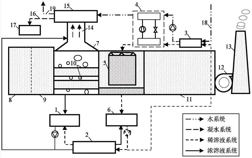
Problems solved by technology

At present, the research of solution dehumidification technology on low-temperature waste heat recovery (such as flue gas, etc.) is mainly limited to using low-temperature waste heat as the driving heat source of solution dehumidification air-conditioning system. During the process, although the heat in the flue gas has been fully recovered and reused, the water vapor and air pollutants have not been effectively treated and recovered.

Method used


Image

  • A device for recovering waste heat and moisture in flue gas

Examples


Embodiment Construction

[0011] The present invention will be described in detail below in conjunction with the accompanying drawings and embodiments.

[0012] like figure 1 As shown, the present invention includes a concentrated solution storage tank 1, a dilute and concentrated solution heat exchanger 2, a solution-water heat exchanger 3, a heat pump 4, a dehumidification and dust collector 5, a dilute solution storage tank 6, a regenerator 7, and an economizer 9 , steam cooling heat exchanger 15 and condensed water collection tank 17. Wherein, the solution outlet of the regenerator 7 is connected with the concentrated solution storage tank 1, and the solution outlet of the concentrated solution storage tank 1 is divided into two branches after the circulation pump, one branch is connected with the inlet of the regenerator 7, and the other branch is It is connected with the concentrated solution inlet of the dilute concentrated solution heat exchanger 2. The concentrated solution outlet of the dil...


PUM


Abstract

The invention relates to a device for recovering waste heat and moisture in flue gas, which comprises a concentrated solution storage tank connected with a regenerator, the solution outlet of the storage tank is respectively connected with the inlet of the regenerator and the concentrated solution inlet of the dilute concentrated solution heat exchanger Connected; the concentrated solution outlet of the dilute concentrated solution heat exchanger is connected with the concentrated solution inlet of the dilute solution storage tank, the solution outlet of the dehumidification dust collector is connected with the inlet of the dilute solution storage tank, and the outlet of the diluted solution storage tank is exchanged with the diluted concentrated solution respectively. The dilute solution inlet of the heater is connected with the solution channel inlet of the solution-water heat exchanger, the dilute solution outlet of the dilute concentrated solution heat exchanger is connected with the dilute solution inlet of the concentrated solution storage tank; the solution outlet of the solution-water heat exchanger is connected through The heat source end of the heat pump is connected to the inlet of the dehumidifier and dust collector; the water channel inlet of the solution-water heat exchanger is connected to the water to be treated, and the water channel outlet is connected to the water channel inlet of the steam cooling heat exchanger through the cold source end of the heat pump. The channel outlet is connected to the user; the steam outlet of the regenerator is connected with the steam inlet of the steam cooling heat exchanger, and the flue gas inlet and outlet of the regenerator are respectively connected with the flue gas outlet of the industrial combustion chamber and the flue gas inlet of the dehumidifier and dust collector.

Description

technical field [0001] The invention relates to a waste heat recovery and utilization system, in particular to a device based on solution dehumidification technology and capable of recovering waste heat and moisture in flue gas. Background technique [0002] The solution dehumidification method is a humidity treatment method that uses the water vapor partial pressure difference between the humid air and the hygroscopic solution to realize the transfer and transfer of moisture. During the process of moisture evaporation, condensation and mass transfer, it is also accompanied by the phase change of the wet air. The heat transfer process with the solution. Compared with the traditional waste heat recovery technology, the solution dehumidification technology requires a lower driving heat source temperature and a simple structure, which can realize independent control of temperature and humidity and purify the air at the same time. It has been rapidly developed and popularized in...

Claims


Application Information

Patent Timeline
Patent Type & Authority Patents(China)
IPC IPC(8): F24F3/14F24F3/16
Inventor 李震刘昕王振英
Owner TSINGHUA UNIV
Learn More