C3 fraction selective hydrogenation method
A selective hydrogenation and fractionation technology, which is applied to hydrocarbons, chemical instruments and methods, purification/separation of hydrocarbons, etc., can solve problems such as increasing the difficulty of operation
- Summary
- Abstract
- Description
- Claims
- Application Information
AI Technical Summary
Problems solved by technology
Method used
Image

Examples
Embodiment 1
[0051] A commercially available bimodal pore distribution cylindrical alumina carrier with a diameter of 4 mm and a length of 4 mm was used. After calcination at 1100°C for 4 hours, the bimodal peaks of pore diameters are at 40nm and 100nm respectively, the pore volume is 0.6ml / g, and the specific surface area is 60m 2 / g.
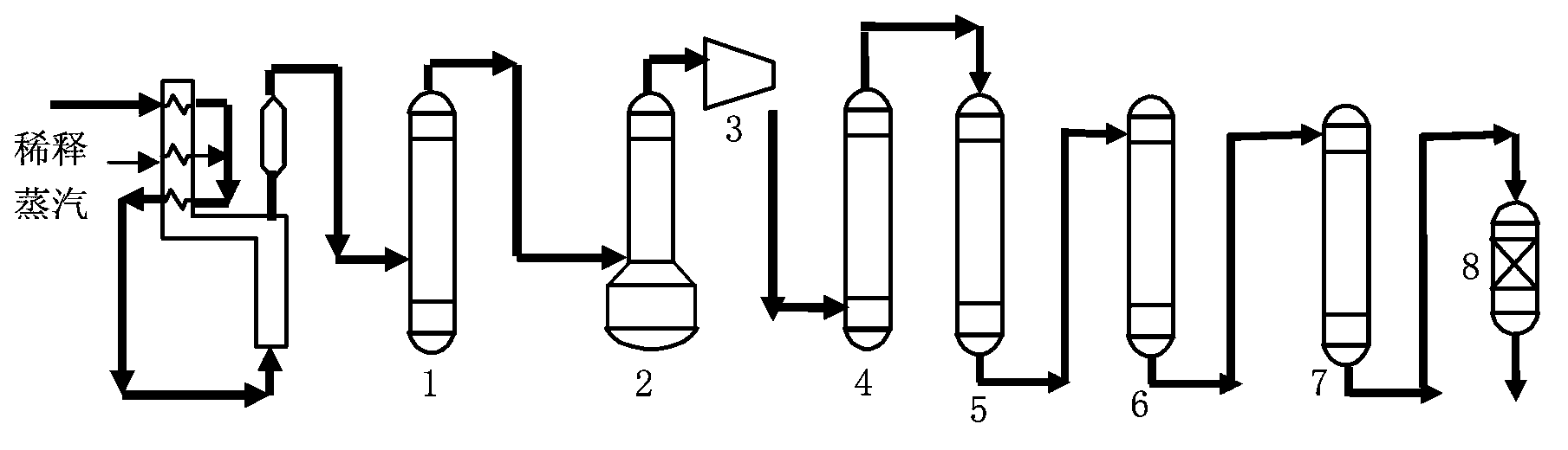
[0052] Its C3 fraction comes from sequential hydrogenation processes such as figure 1 As shown, but the reaction bed of the adiabatic bed reactor is divided into two sections, and the raw material composition is shown in Table 1.
[0053] Table 1 hydrogenation raw material composition
[0054] Hydrogenation feedstock
C 3 h 4 (MA)
C 3 h 4 (PD)
C 3 h 6
C 3 h 8
Content (v / v%)
4.8
3.2
82.0
10.0
[0055] Reaction conditions:
[0056] Two-stage adiabatic bed reactor hydrogenation process, liquid phase raw material volume space velocity: 5h -1 , Operating pressure: 2.5MPa, reactor catalys...
Embodiment 2
[0058] A commercially available bimodal pore distribution spherical alumina carrier with a diameter of 4 mm was used. After calcination at 1050°C for 4 hours, the bimodal peaks of pore diameters are at 20nm and 150nm respectively, the pore volume is 0.4ml / g, and the specific surface area is 70m 2 / g.
[0059] use figure 1 The technological process shown, its C3 fraction raw material composition is as shown in Table 2.
[0060] Table 2 hydrogenation raw material composition
[0061] Hydrogenation feedstock
[0062] Single-stage reactor hydrogenation process, liquid phase raw material volume space velocity: 50h -1 , Operating pressure: 3.5MPa, reactor catalyst loading: 300ml, hydrogen / (MA+PD) (mol)=5:1, reactor inlet temperature 25°C. The reaction results after 1000 hours of assessment are shown in Table 5.
Embodiment 3
[0064] A commercially available bimodal pore distribution four-leaf clover-shaped alumina carrier was used, with a diameter of 5.5 mm and a length of 4 mm. After calcination at 1000°C for 4 hours, the bimodal peaks of pore diameters are 30nm and 200nm respectively, the pore volume is 0.5ml / g, and the specific surface area is 80m 2 / g.
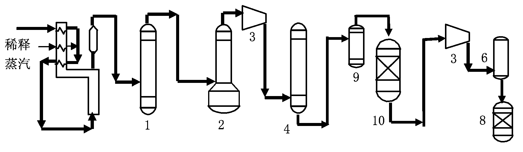
[0065] use figure 2 The technological process shown, its C3 fraction raw material composition is as shown in Table 5.
[0066] Table 3 hydrogenation raw material composition
[0067] Hydrogenation feedstock
C 3 h 4 (MA)
C 3 h 4 (PD)
C 3 h 6
C 3 h 8
Content (mol%)
0.1
0.1
85.0
14.80
[0068] Reaction process conditions: single-stage adiabatic bed reactor process, material space velocity: 100h -1 , Operating pressure: 3.0MPa, catalyst loading: 200ml. Hydrogen / (MA+PD)(mol)=1:1. The reaction results after 600 hours of assessment are shown in Table 6.
[0069] Embodiment ...
PUM
| Property | Measurement | Unit |
|---|---|---|
| Particle size | aaaaa | aaaaa |
Abstract
Description
Claims
Application Information
PatSnap Eureka turns technology decisions into work you can execute. Powered by our Innovation Knowledge Graph, it runs expert workflows across engineering, life sciences, materials and intellectual property. Get your review-ready output in minutes.


