X-waveband radar receiver front end active low noise mixer
A receiver front-end and mixer technology, applied in instruments, radio wave measurement systems, diode modulation conversion, etc., to achieve good performance parameters, improve initial bias, and facilitate mass production
- Summary
- Abstract
- Description
- Claims
- Application Information
AI Technical Summary
Problems solved by technology
Method used
Image
Examples
Embodiment 1
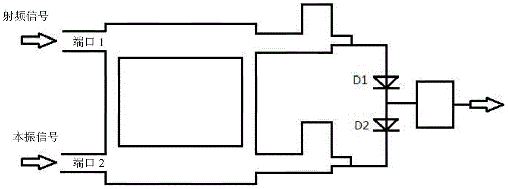
[0033] Such as figure 1 Shown is the circuit topology diagram of the X-band low noise mixer of the present invention. The mixer is composed of a directional coupler, a matching circuit, a mixing diode and a low-pass filter. The RF signal is added from the input port 1 of the directional coupler, and the local oscillator signal is added from the other input port 2 of the directional coupler. The directional coupler ensures proper isolation between the local oscillator port and the signal port. Generally, the isolation is 10dB and the coupling is 3dB. There is a 1 / 4 wavelength impedance converter between the directional coupler and the mixer tube to complete impedance matching, so that the signal and local oscillator power are equally divided into the mixer diode. The circuit requires the hybrid circuit to enable both the RF signal and the local oscillator signal to be applied to the mixing diode with equal power and a 90° phase difference.
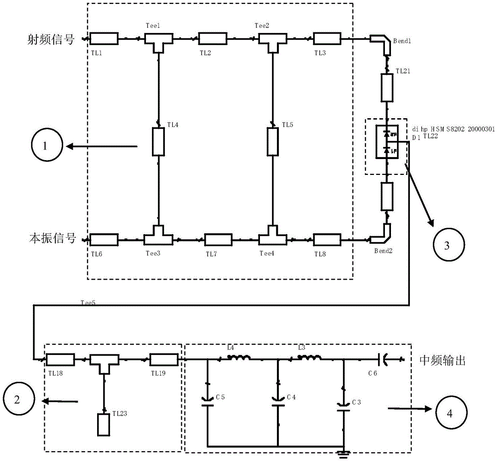
[0034] Such as figure 2 Shown ...
Embodiment 2
[0038] Such as Figure 4 As shown, in order to optimize the performance and reduce the noise figure, the X-band active low-noise mixer of the present invention adopts the method of adding a DC bias circuit in the first embodiment, and the specific form is a fan-shaped microstrip line DC bias circuit. ⑤ is a DC bias circuit, which is composed of a DC voltage source, a bias voltage access point, a quarter-wavelength microstrip line for inputting radio frequency signals, and a fan-shaped microstrip line with a quarter-wavelength radius. The voltage source is connected to the bias voltage access point ⑨, the bias voltage access point ⑨ is connected to the quarter-wavelength microstrip line and the quarter-wavelength fan-shaped microstrip line, and the other end of the quarter-wavelength microstrip line ⑩ Access to the main circuit, the access point on the main circuit is located at the two output ports of the directional coupler. Since the fan-shaped edge is open, the RF signal c...
Embodiment 3
[0042] Such as Figure 7 As shown, the X-band active low-noise mixer of the present invention is modified for the second time on the basis of the second embodiment. The correction step is to change one of the forward bias voltages in ⑤ to the reverse bias voltage in ⑥ to get more optimized performance.
[0043] Such as Figure 8 As shown, it is the circuit schematic diagram after the second revision of the X-band active low-noise mixer of the present invention, and the improvements are as follows: Figure 7 The corrected bias circuit is connected to the output port below the directional coupler, which further reduces the noise figure of the whole system.
[0044] Such as Figure 9Shown is the frequency conversion loss and noise figure after the second correction of the X-band active low-noise mixer of the present invention. After adopting the optimization method of adding forward and reverse bias circuits, and by using ADS software simulation, it can be seen that the noise...
PUM
 Abstract
Description
Claims
Application Information
 - R&D
- Intellectual Property
- Life Sciences
- Materials
- Tech Scout
- Unparalleled Data Quality
- Higher Quality Content
- 60% Fewer Hallucinations
Browse by: Latest US Patents, China's latest patents, Technical Efficacy Thesaurus, Application Domain, Technology Topic, Popular Technical Reports.
© 2025 PatSnap. All rights reserved.Legal|Privacy policy|Modern Slavery Act Transparency Statement|Sitemap|About US| Contact US: help@patsnap.com


