Spinning forming device for metal thin-walled cylindrical workpiece

A cylindrical workpiece, spinning forming technology, applied in metal processing equipment, feeding devices, positioning devices, etc., can solve the problems of low processing efficiency, inability to guarantee work processing accuracy, etc., and achieve convenient assembly, reliable rotation, and stable positioning. Effect

Active Publication Date: 2016-08-24
WUXI DAWN DIE & STAMPING
View PDF9 Cites 0 Cited by
  • Summary
  • Abstract
  • Description
  • Claims
  • Application Information

AI Technical Summary

Problems solved by technology

[0003] In view of the above problems, the present invention provides a spinning forming device structure for metal thin-walled cylindrical workpieces, which can solve the problems that the traditional one-by-one spinning method cannot guarantee the working precision and low processing efficiency. Easy to uninstall

Method used


Image

  • Spinning forming device for metal thin-walled cylindrical workpiece
  • Spinning forming device for metal thin-walled cylindrical workpiece
  • Spinning forming device for metal thin-walled cylindrical workpiece

Examples


Embodiment Construction

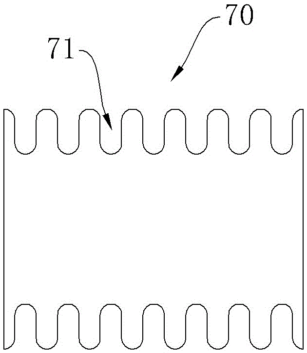
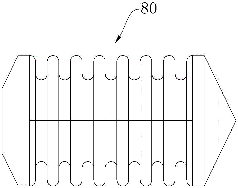
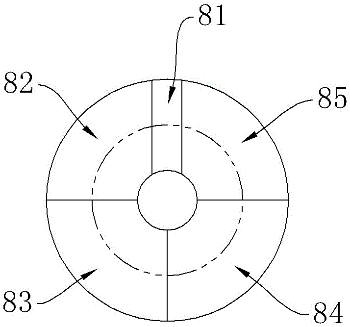
[0034] See Figure 5 , Image 6 , Figure 7 , Figure 8 , Figure 9with Figure 10 The spinning forming device of the present invention includes a mandrel 10 and a spinning die, the spinning die includes a forming die 20 and a beading roller 40, the mandrel 10 passes through the shaft hole 210 of the forming die 20, and the forming die 20 is tightened by a positioning fastening device Fixed on the mandrel 10, the mandrel 10 is connected with the main shaft of the machine tool. During the spinning process, the forming die 20 rotates with the mandrel under the drive of the main shaft of the machine tool. The outer peripheral surface of the forming die 20 is provided with a forming surface 25. 40 is installed on the knife rest of lathe by beading wheel support 50, and the outer peripheral surface of beading roller 40 is the beading profile 42 that matches with whole forming surface, and beading roller 40 is axially parallel with forming die 20 and faces.

[0035] The beading...


PUM


Abstract

The invention provides a spinning forming device structure for metal thin-walled cylindrical workpieces, which can solve the problems of inability to guarantee working precision and low processing efficiency in traditional one-by-one spinning methods, and at the same time, unload the workpieces after the spinning processing is completed. It includes a mandrel and a spinning die. The spinning die includes a forming die and a bead roller. The mandrel runs through the shaft hole of the forming die. The forming die is fastened to the mandrel by a positioning fastening device, and the mandrel is connected to the main shaft of the machine tool through transmission. , during spinning, the forming mold rotates with the mandrel under the drive of the main shaft of the machine tool, and the outer periphery of the forming mold is provided with a forming surface. The outer peripheral surface of the machine is a beading profile matching the entire forming surface, and the beading roller is parallel to and facing the axis of the forming die.

Description

technical field [0001] The invention relates to the field of spinning die structure, in particular to the field of spinning forming of metal thin-walled cylindrical work, in particular to a spinning forming die structure of metal thin-walled cylindrical workpiece. Background technique [0002] Spinning is to fix the flat or hollow blank on the mold of the spinning machine. While the blank is rotating with the main shaft of the bed, the blank is pressed with a spinning wheel or a driving rod to cause local plastic deformation. Under the joint action of the feed motion of the rotary wheel and the rotational motion of the blank, the local plastic deformation is gradually extended to the entire surface of the blank, and it is closely attached to the mold. The spinning process carried out under normal temperature conditions is called cold spinning. . Spinning products have a variety of shapes. Through spinning, various tasks such as forming, reducing diameter, closing, back seal...

Claims


Application Information

Patent Timeline
Patent Type & Authority Patents(China)
IPC IPC(8): B21D22/16B21D43/00
Inventor 庄本段玉霞曹一枢
Owner WUXI DAWN DIE & STAMPING
Why Eureka
Try Eureka