An exhaust gas recovery, purification and recycling device and process for an annealing furnace system

A tail gas recovery and purification cycle technology, which is applied to the improvement of process efficiency, furnaces, furnace components, etc., can solve the problems that impurities cannot be effectively processed, increase equipment production costs, and increase processing problems, so as to ensure smooth flow and reduce maintenance rate , the effect of avoiding pollution

Inactive Publication Date: 2016-03-09
苏州为众气体设备有限公司
View PDF11 Cites 0 Cited by
  • Summary
  • Abstract
  • Description
  • Claims
  • Application Information

AI Technical Summary

Problems solved by technology

[0003] The first type: as disclosed in the Chinese patent (CN101956061B), the bell-type bright annealing furnace protective gas recovery and recycling process and its device are to pretreat the tail gas by cold treatment, but this process cannot effectively process the impurities in the tail gas. It will cause pollution of equipment pipelines, failure of adsorbents, etc., and increase equipment maintenance costs
[0004] The second type: as disclosed in a Chinese patent (CN102538488B), a tail gas purification and recycling device and process for a bell-type bright annealing furnace system is pretreated by rinsing to deal with the problem of impurities in the tail gas, but it will be brought into Saturated water, which increases the subsequent processing problems and increases the production cost of the equipment

Method used


Image

  • An exhaust gas recovery, purification and recycling device and process for an annealing furnace system
  • An exhaust gas recovery, purification and recycling device and process for an annealing furnace system
  • An exhaust gas recovery, purification and recycling device and process for an annealing furnace system

Examples


Embodiment 1

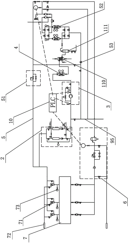
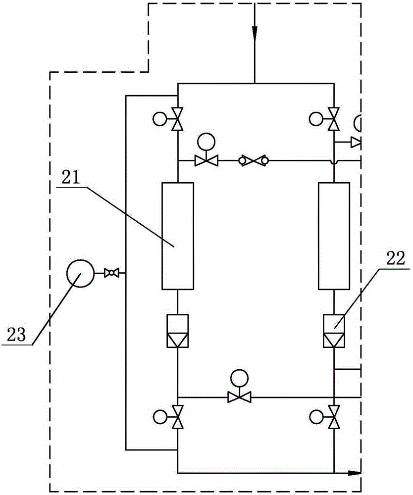
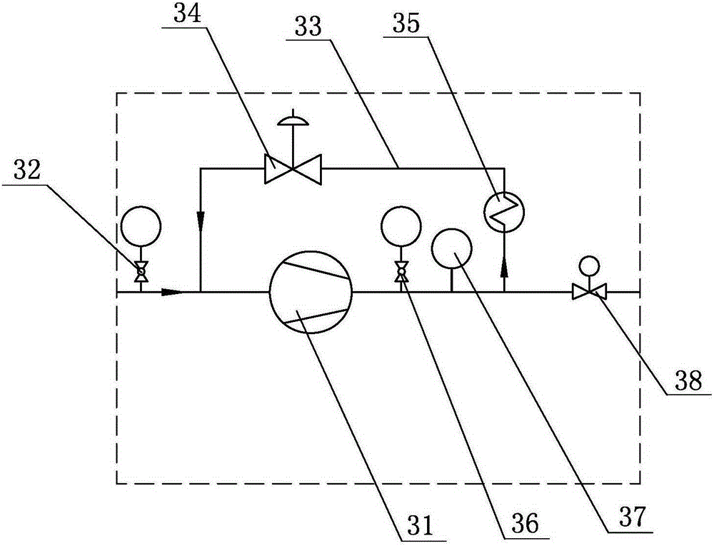
[0045] Example one: such as Figure 1~4 As shown, an exhaust gas recovery and purification recycling device of an annealing furnace system includes an adsorption purification device 2, a circulating power device 3, a catalytic purification device 4, a first cooler 110, a gas-water separator 111, an adsorption drying device, and connection In the pipeline between the parts, the air inlet of the adsorption purification device 2 is connected to the exhaust outlet of the annealing furnace 7, and the air outlet of the adsorption purification device 2 is connected to the circulating power device 3. The air outlet is connected to the first cooler 110, the gas-water separator 111 and the adsorption drying device in sequence after the catalytic purification device 4, and the air outlet of the adsorption drying device is connected to the air inlet of the annealing furnace 7 through the pipeline, so A first pressure regulating device 6 is provided on the pipeline.

[0046] A constant press...

Embodiment 2

[0062] Embodiment 2: A tail gas recovery and purification recycling device of an annealing furnace system, including an adsorption purification device, a circulating power device, a deaerator, a first cooler, a gas-water separator, an adsorption drying device, and a connection between each part Pipeline, the air inlet of the adsorption purification device is connected to the exhaust outlet of the annealing furnace, the air outlet of the adsorption purification device is connected to the circulating power device, and the air outlet of the circulating power device is sequentially connected after the deaerator Connected to the first cooler, the gas-water separator and the adsorption drying device, the air outlet of the adsorption drying device is connected to the air inlet of the annealing furnace through a pipeline, and the pipeline is provided with a first pressure regulating device.

[0063] In this embodiment, its structure is basically similar to that of the first embodiment. Th...

Embodiment 3

[0064] Example three: such as Figure 5 , 6 As shown, a tail gas recovery and purification recycling device of an annealing furnace system. In this embodiment, its structure is basically similar to that of the first embodiment. The difference lies in: the annealing furnace tail gas discharge port and the adsorption purification device 2 There is also a dust-removing and oil-collecting device 1 on the pipeline between them. The dust-removing and oil-collecting device 1 includes a front and a rear two-stage oil collector, a first-stage oil collector 11 and a second-stage oil collector 12, respectively. A cleaning port is provided, a cooling jacket is also provided on the outer wall of the oil collector, and bypass valves 13 are respectively provided on the inlet and outlet of the two-stage oil collector, such as Image 6 Shown. When working, the exhaust gas is blown into the oil collector in a direction tangential to the oil collector, and rotates along the inner wall of the oil c...


PUM


Abstract

The invention discloses a tail gas recovery purification recycling device of an annealing furnace system. The tail gas recovery purification recycling device of the annealing furnace system is characterized by comprising components of an adsorption purification device, a circulation power device, a catalysis purification device or a deoxidizing device, a first cooling device, an air and water separator, and an adsorption drying device, and further comprising a pipeline connected among all the components, wherein all the components are sequentially connected through the pipeline, an air inlet of the adsorption purification device is connected with a tail gas outlet of an annealing furnace, an air outlet of the adsorption drying device is connected with an air inlet of the annealing furnace through the pipeline, and a first pressure adjustment device is arranged on the pipeline. The tail gas recovery purification recycling technology of the annealing furnace system is characterized in that tail gas sequentially passes through the adsorption purification device, the circulation power device, the catalysis purification device, the first cooling device, the air and water separator and the adsorption drying device from the tail gas outlet of the annealing furnace, and finally enters the air inlet of the annealing furnace through the first pressure adjustment device. The tail gas recovery purification recycling device and the tail gas recovery purification recycling technology of the annealing furnace system achieve purification treatment of the tail gas of the annealing furnace, and the tail gas after the purification treatment can be recycled, and therefore energy consumption is effectively reduced.

Description

Technical field [0001] The invention relates to a bell-type bright annealing furnace or continuous annealing furnace, in particular to a tail gas recovery, purification and recycling device and process of an annealing furnace system, and is mainly used for tail gas treatment of the bell-type bright annealing furnace or continuous annealing furnace. Background technique [0002] At present, the protective gas used for the bell-type bright annealing furnace is mainly pure hydrogen, and the tail gas is basically directly burned or vented to the atmosphere. Some manufacturers only use part of the gas as combustion gas to burn and recover heat, which is not only a waste Has lost energy and is very unsafe. There are mainly two types of exhaust gas recovery, purification and recycling processes in the existing bell-type bright annealing furnace system: [0003] The first type: as disclosed in the Chinese patent (CN101956061B), the protective gas recovery and recycling process of the bell...

Claims


Application Information

Patent Timeline
Patent Type & Authority Patents(China)
IPC IPC(8): F27D17/00
CPCY02P10/25
Inventor 郭杰程长圣刘春吴云南
Owner 苏州为众气体设备有限公司
Why Eureka
Try Eureka