An integrated downdraft biomass gasification power generation system and method

A power generation system, biomass technology, applied in the gasification process, gasification device details, chemical industry, etc., can solve the problems of high tar content of combustible gas, low energy utilization rate, large and complex system, etc., to improve operating efficiency, Good production environment and high economical effect

Active Publication Date: 2020-06-23
青岛德瑞汇丰环保科技股份有限公司
View PDF5 Cites 0 Cited by
  • Summary
  • Abstract
  • Description
  • Claims
  • Application Information

AI Technical Summary

Problems solved by technology

[0007] 2. The thermal efficiency of the miniaturized biomass gasification power generation system currently on the market is low, and the energy utilization rate is only 20%-30%
Moreover, the system is complex, the floor area is too large, and the investment cost is high
[0008] 3. The effect of the reactor in the existing miniaturized biomass gasification power generation system on the market is poor, and the content of combustible gas tar generated is relatively high
It is necessary to set up filter equipment such as sprinklers and electric coke catchers for purification, and the system is too large and complicated
[0009] 4. The existing miniaturized biomass gasification power generation system on the market will produce a large amount of tar-containing sewage, causing secondary pollution

Method used


Image

  • An integrated downdraft biomass gasification power generation system and method
  • An integrated downdraft biomass gasification power generation system and method
  • An integrated downdraft biomass gasification power generation system and method

Examples


Embodiment Construction

[0051] The specific embodiments of the present invention will be described in detail with reference to the accompanying drawings.

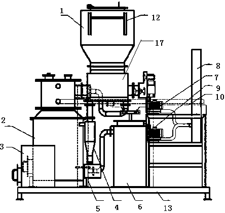
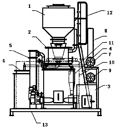
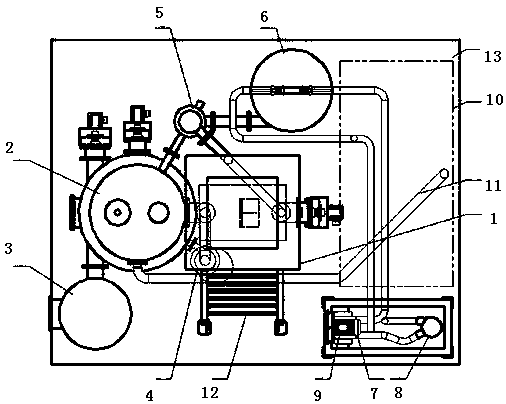
[0052] Such as figure 1 , 2 , 3 and 4, an integrated downdraft biomass gasification power generation system, including a hopper 1, a reactor 2, a dust removal device 4, an air preheater 5, an activated carbon adsorber 6, a gas The fan 7, the torch 8, the air fan 9, the gas generator set 10, and the base 13. The hopper 1 includes a drying chamber 17 and a conveying device 14. The wall of the drying chamber 17 is composed of two layers of shells. A jacketed cavity is formed between the bodies. The conveying device 14 conveys the materials in the drying chamber 17 to the reactor 2. The gas outlet of the reactor 2 is connected to the gas inlet of the dust removal device 4, and the dust removal device 4 The gas outlet of the air preheater 5 is connected to the gas inlet of the hopper drying chamber 17, the gas inlet of the air preheater 5 is connected to ...


PUM


Abstract

The invention discloses an integrated downdraft biomass gasification power generation system, belongs to the technical field of biomass gasification power generation, and particularly relates to an integrated downdraft biomass gasification power generation system and method. The system comprises a hopper, a reactor, a slag barrel, a cyclone dust remover, an air preheater, an activated carbon adsorber, a gas fan, a torch, an air fan, a gas generator set, a pipeline, a ladder and a base, and is characterized in that the hopper, the air preheater, the cyclone dust remover, the slag barrel and thereactor are coupled into a compact whole, so that the heat efficiency of the whole system is greatly improved. The system is suitable for gasifying straw particles, wood chips, crushed coconut shellsand other carbonaceous biomass materials to generate combustible gas, and the combustible gas is conveyed into a gas engine to be combusted to push the engine to drive a generator to generate electric energy. The system is compact in structure, high in universality, high in energy utilization rate, reliable, convenient to use and easy to operate.

Description

Technical field [0001] The invention belongs to the technical field of biomass gasification and power generation, and specifically is an integrated downdraft biomass gasification and power generation system and method. Background technique [0002] Biomass is the fourth largest energy resource after coal, oil, and natural gas. It is an environmentally friendly renewable resource, accounting for 14% of the world's total energy consumption. In order to fully exploit the material energy and improve my country’s energy structure, the state promulgated and implemented the "Renewable Energy Law" in 2006 to encourage and support the development and utilization of renewable energy, and provide a series of financial discounts for renewable energy development and utilization projects. Tax incentives. [0003] Jiangsu Province is the province with the most biomass power plants in my country. According to the survey, since the State promulgated and implemented the "Renewable Energy Law" in 20...

Claims


Application Information

Patent Timeline
Patent Type & Authority Patents(China)
IPC IPC(8): C10J3/64C10J3/72C10J3/80C10J3/84
CPCC10J3/64C10J3/72C10J3/723C10J3/725C10J3/80C10J3/84C10J2200/152C10J2300/0909C10J2300/0916C10J2300/1223C10J2300/1671Y02P20/10Y02P20/129
Inventor 张瑞亮
Owner 青岛德瑞汇丰环保科技股份有限公司
Why Eureka
Try Eureka