
Linear scanning-based fluorescence confocal detection device

A detection device and confocal technology, applied in fluorescence/phosphorescence, material excitation analysis, etc., can solve the problems of stray light interference detection, low detection limit, unsatisfactory signal-to-noise ratio, etc., to improve detection frequency and detection accuracy, eliminate The effect of interference and improved detection sensitivity

Active Publication Date: 2014-10-22
TSINGHUA UNIV
View PDF6 Cites 7 Cited by
  • Summary
  • Abstract
  • Description
  • Claims
  • Application Information

AI Technical Summary

Problems solved by technology

Since its imaging is aimed at the entire sample surface, high-throughput detection can be performed, but the limitations of this detection method are also obvious: 1. It is not a confocal system, the signal-to-noise ratio is not ideal, and the detection limit is low; 2. Since the entire plane is imaged, points without fluorescent signals on the plane will have more stray light interference detection; 3. Some software is needed to analyze the collected images and extract signal points, and the software calculation is limited by computer speed , so there is a certain limitation in the timeliness of detection

Method used


Image

  • Linear scanning-based fluorescence confocal detection device
  • Linear scanning-based fluorescence confocal detection device
  • Linear scanning-based fluorescence confocal detection device

Examples


Embodiment Construction

[0025] The present invention will be further described below in conjunction with the accompanying drawings, but the present invention is not limited to the following embodiments.

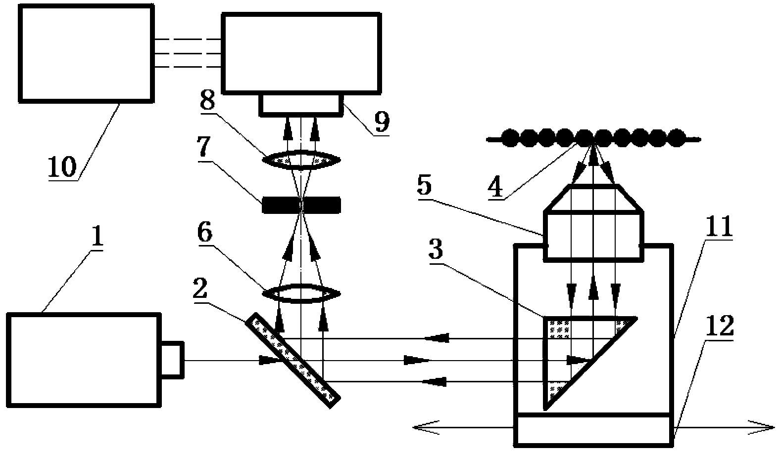
[0026] Such as figure 1 As shown, in the fluorescent confocal detection device provided by the present invention, firstly, the sample to be tested has a fluorescent label, and the labeled fluorescent light can emit a fluorescent signal when excited by a laser with a specific wavelength and power. A laser with a fixed wavelength can be selected for specific fluorescently labeled samples (for example, only for the detection of one or several fluorescent signals), or a laser with an adjustable wavelength can be selected to enable the instrument to detect more different samples. A dichroic prism 2 that is 135° to the optical path is set on the optical path of the excitation light emitted by the laser 1; the optical path of the transmitted light after the excitation light is transmitted through the dichr...


PUM


Abstract

The invention discloses a linear scanning-based fluorescence confocal detection device. The linear scanning-based fluorescence confocal detection device is characterized in that a dichroic prism is arranged in an optical path of an exciting light beam and forms an angle of 135 degrees with the optical path, a rectangular prism is arranged in an optical path of the exciting light transmitted by the dichroic prism and forms an angle of 45 degrees with the optical path, the transmission light is reflected to an object lens by the rectangular prism and then is focused to a sample so that an optical signal is obtained, the optical signal goes through the object lens, then is orderly reflected by the rectangular prism and the dichroic prism, then orderly goes through an optical lens I, a pinhole and an optical lens II and then is parallelly transmitted to an optical detector so that an optical signal, a spectrum signal or an optical intensity signal of the sample is obtained, and the rectangular prism and the object lens can carry out rectilinear motion along an exciting light incident direction. Through combination of the traditional confocal system and a scanning platform, the confocal system can realize multichannel scanning of a lot of samples. The linear motor scanning platform carries out scanning so that detection frequency and a detection precision are improved.

Description

technical field [0001] The invention relates to a fluorescence confocal detection device based on linear scanning. Background technique [0002] Since the beginning of the 21st century, biochip technology has developed rapidly, and its high-throughput, miniaturization, and automation characteristics have put forward relatively high requirements for related supporting instruments. The confocal optical system means that the excitation light is focused on the sample surface while the emitted light is concentrated on the pinhole, and the focus depth of the system on the sample surface is limited by the pinhole to reduce the signal intensity of the background light, thereby greatly improving the signal-to-noise ratio of the system and detection limit. General confocal scanning microscopes use gratings to expand the converging range of excitation light to image samples in the field of view. However, limited by the size of the objective lens and pinholes, the detection range is sm...

Claims


Application Information

Patent Timeline
Patent Type & Authority Applications(China)
IPC IPC(8): G01N21/64
Inventor 刘鹏庄斌王帅钦甘五鹏
Owner TSINGHUA UNIV
Learn More